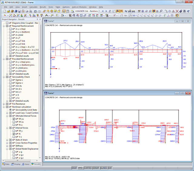
After the calculation, the module shows clearly arranged tables listing the required reinforcement and the results of the serviceability limit state design. All intermediate values are included in a comprehensible manner. In addition to the tables, current stresses and strains in a cross‑section are represented graphically.
The reinforcement proposals of the longitudinal and the shear reinforcement, including sketches, are documented in accordance with current practice. It is possible to edit the reinforcement proposal and to adjust, for example, the number of members and the anchorage. The modifications will be updated automatically.
A concrete cross‑section, including reinforcement, can be visualized in a 3D rendering. This way, the program provides an optimal documentation option to create reinforcement drawings, including steel schedule.
Crack width analyzes are performed using the selected reinforcement of internal forces in the serviceability limit state. The result output covers steel stresses, the minimum reinforcement, limit diameters, and the maximum bar spacing, as well as crack spacing and the maximum crack widths.
As a result of the nonlinear calculation, there are the ultimate limit states of the cross‑section with defined reinforcement (determined linear elastically) as well as effective deflections of the member considering stiffness in cracked state.

The members to be designed are directly imported from RFEM/RSTAB. Load cases, load combinations, and result combinations are assigned, which result in the linear-elastically determined internal forces on the selected members. When considering creeping, the creep-producing load must also be defined. The RFEM/RSTAB materials are preset but can be adjusted in RF-/CONCRETE Columns. The material properties listed in the respective standard are included in the material library.
You can easily define constructional properties of columns as well as other details for determining the required longitudinal and shear reinforcement. The effective length factor ß is to be defined manually, determined automatically by the module, or imported from the RF-STABILITY/RSBUCK add-on module.
The fire resistance design according to EN 1992-1-2 requires various specifications; for example, determination of cross-section sides where burn-off occurs.