
In this tutorial, we would like to inform you about the essential features of the RFEM program. The first part shows how to create the structural objects and loads, combine the loads, perform a structural analysis, check the results, and prepare the data for printing. Eurocodes with the CEN settings are used as standards.
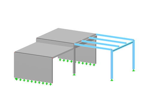
In this tutorial, we would like to inform you about the essential features of the RFEM program. The first part shows how to create the structural objects and loads, combine the loads, perform a structural analysis, check the results, and prepare the data for printing. The US codes are used as standards.
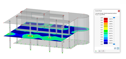
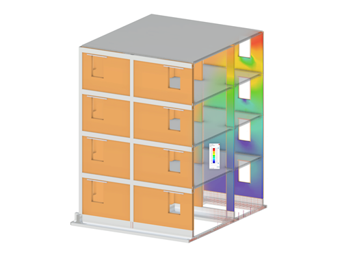
The Concrete Design add-on allows you to design reinforced concrete members and surfaces according to various design standards. It is possible to perform the ultimate limit state and serviceability limit state design checks. The input and result evaluation are completely integrated in the user interface of the structural FEA software RFEM and the frame & truss analysis software RSTAB.
This manual describes the Concrete Design add-on for RFEM 6 and RSTAB 9. In RSTAB, you can only design members and member sets, not surfaces.
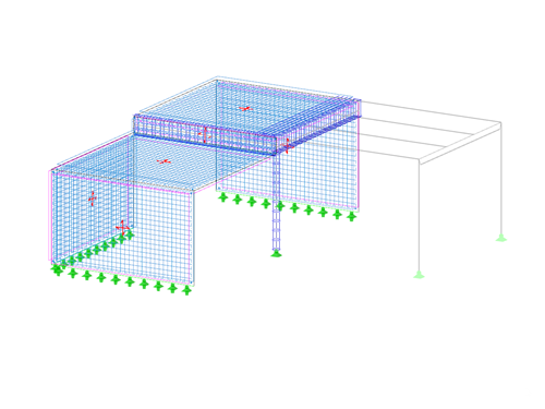
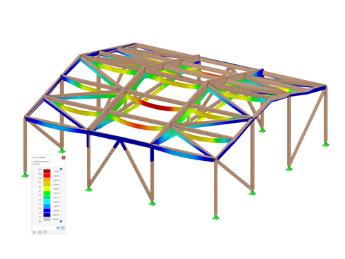
In this tutorial, we would like to inform you about the essential features of the RFEM program. In the first part, a model was defined and a structural analysis was carried out. The second part deals with the concrete design of the slabs, walls, beams, and the column according to EN 1992‑1‑1 with the CEN settings.
In this tutorial, we would like to inform you about the essential features of the RFEM program. In the first part, a model was defined and a structural analysis was carried out. Now, the second part deals with the concrete design of slabs, walls, beams, and the column. ACI 318-19 is used as a standard.
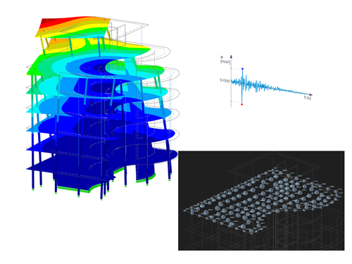
Dynamic analyses in RFEM 6 and RSTAB 9 can be performed in several add-ons.
- The Modal Analysis add-on is the basic add-on, performing natural vibration analyses for member, surface, and solid models. It is a prerequisite for all other dynamic add-ons.
- The Response Spectrum Analysis add-on allows you to perform a seismic analysis using the multi-modal response spectrum analysis.
- The Time History Analysis add-on allows for a dynamic structural analysis of external excitations that can be defined as a function of time.
- The Pushover Analysis add-on allows you to determine the maximum nonlinear response of a structure to seismic loads.
- The Harmonic Response Analysis add-on is still under development.
This manual describes the dynamic analysis add-ons for RFEM 6 and RSTAB 9.
The Timber Design add-on allows you to design timber members and surfaces according to various design standards. Cross-section resistance checks, stability analyses, and serviceability limit state design checks can also be performed. The input and result evaluation are completely integrated in the user interface of the structural FEA software RFEM and the frame & truss analysis software RSTAB.
This manual describes the Timber Design add-on for the RFEM 6 and RSTAB 9 programs.
The Masonry Design add-on activates special material models that have been developed for calculating masonry structures. This allows you to consider the masonry material in an FEM analysis.
In the calculation, internal forces and deformations are determined on the basis of stress-strain lines derived from the standardization. This means that the design is based on the standard.
This manual describes the Masonry Design add-on for the RFEM 6 program.
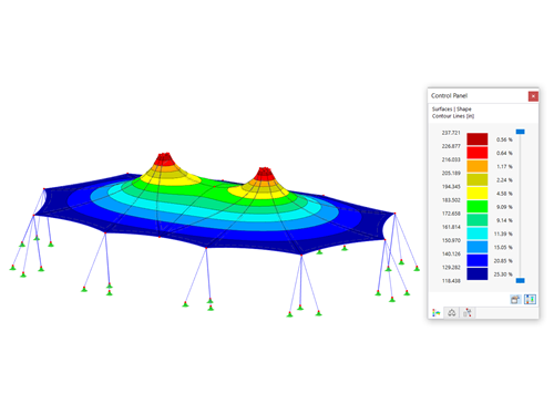
The Form-Finding add-on finds the optimal shape of members subjected to axial forces and tension-loaded surface models. The shape is determined by the equilibrium between the member axial force or the membrane stress and the existing boundary conditions.
The resulting new model shape with impressed force conditions is made available as a universally applicable initial state for further calculation of the entire structure.
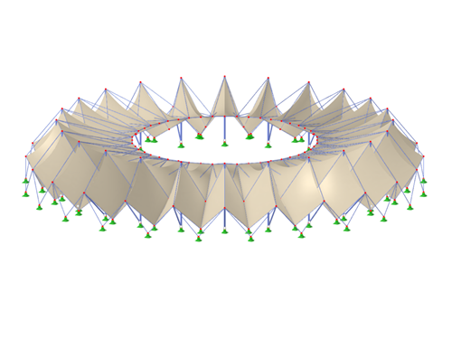
This manual describes the modeling of a stadium roof made of membranes in RFEM 6. Since the model consists of several segments, the creation of the individual segments is shown. Each segment consists of a main structure (a column, a stiffening element, cables) and a secondary structure (a membrane).