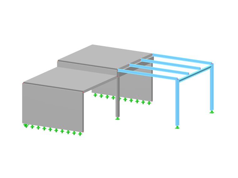
In this tutorial, we would like to inform you about the essential features of the RFEM program. The first part shows how to create the structural objects and loads, combine the loads, perform a structural analysis, check the results, and prepare the data for printing. Eurocodes with the CEN settings are used as standards.
Online Manuals
RFEM 6 | Tutorial - Structural Analysis
![Steel Hall](/en/webimage/032075/3327947/EN_1.png?mw=512&hash=ab89cd9cb5658abc8b4719242f1c9e322c29cd8a)
This article will show you how to use the Torsion Warping (7 DOF) add-on in combination with the Structure Stability add-on to consider cross-section warping as an additional degree of freedom when performing the stability analysis.
![Steel Hall](/en/webimage/032075/3327947/EN_1.png?mw=512&hash=ab89cd9cb5658abc8b4719242f1c9e322c29cd8a)
This article will show you a practical example of how to determine critical load factors and corresponding mode shapes in RFEM 6.
![KB 001885 | Assessment of Story Drift under Seismic Loads According to ASCE 7-22 and the Building Model](/en/webimage/051645/3995306/im1.png?mw=512&hash=b8237709c4f30213fac51d86d32a42bddde72f03)
The evaluation of story drift in a building is crucial to ensure acceptable structural performance by limiting the drift amount. Excessive drift has the potential to induce system instability and may cause damage to nonstructural components such as partitions. This article outlines the procedure for establishing interstory drift according to ASCE 7-22 and the Building Model add-on in RFEM 6.
![KB 001883 | Plate Girder Design According to AISC 360-22 in RFEM 6](/en/webimage/051561/3980997/im1.png?mw=512&hash=b8237709c4f30213fac51d86d32a42bddde72f03)
Plate girder is an economical choice for long spans construction. I-section steel plate girder typically has a deep web to maximize its shear capacity and flange separation, yet thin web to minimize the self-weight. Due to its large height-to-thickness (h/tw) ratio, transverse stiffeners may be required to stiffen the slender web.
![Feature 002854 | Transfer of support reactions to free loads](/en/webimage/051684/3998606/1.png?mw=512&hash=9d7f6c198b6d4ae6ee8f2fa8bca75f85579e14c9)
In the "Import Support Reaction" load wizard, the "Free Loads" object connection type is available in addition to the "Manual" ones. This option saves you the task of manually assigning the support reactions to specific nodes and lines. The support forces of the connected model are applied as free loads in this option.
![Feature 002852 | Spline surface with minimum curvature](/en/webimage/051665/3996349/2.png?mw=512&hash=495637ed9f78ff76e0ac09e73585e9001cb15ebb)
You can use the "spline with minimum curvature" surface geometry type to generate curved surfaces on the basis of the control nodes in the middle of the surface.
This can be used to model terrain surfaces, for example.
![Feature 002853 | Design check details about mesh node selection in graphics](/en/webimage/051681/3998147/1.png?mw=512&hash=9d7f6c198b6d4ae6ee8f2fa8bca75f85579e14c9)
In the result diagrams in the surface point, you can simply select the mesh nodes in the graphic to display the detailed results at this point.
![Add-on "Steel Joints for RFEM 6" | Component Library](/en/webimage/043097/3898884/steel_joints_components.png?mw=512&hash=e4f835906155863fc7019d5043b22e553dc766f9)
- Numerous component types, such as base and end plates, web angles, fin plates, gusset plates, stiffeners, tapers, or ribs for easy input of typical connection situations
- Universally applicable basic components (such as plates, welds, bolts, auxiliary planes) for modeling complex connection situations
- Graphical display of the connection geometry with dynamic updating during the input
- Wide range of cross-section shapes: I-sections, U-sections, angles, T-sections, hollow sections, built-up cross-sections and thin-walled sections
- Library in Dlubal Center with program template connections as well as user-defined templates
- Automatic adaptation of the connection geometry based on the relative arrangement of the components to each other – even in case of subsequent editing of the structural components