
The design of cold-formed steel members according to the AISI S100-16 / CSA S136-16 is available in RFEM 6. Design can be accessed by selecting “AISC 360” or “CSA S16” as the standard in the Steel Design Add-on. “AISI S100” or “CSA S136” is then automatically selected for the cold-formed design.
RFEM applies the Direct Strength Method (DSM) to calculate the elastic buckling load of the member. The Direct Strength Method offers two types of solutions, numerical (Finite Strip Method) and analytical (Specification). The FSM signature curve and buckling shapes can be viewed under Sections.

Wind loads are also not a problem in your design. You can automatically generate wind loads as member loads or area loads (RFEM) on the following structural components:
- Vertical walls
- Flat roofs
- Monopitch roofs
- Duopitch/troughed roofs
- Vertical walls with duopitch roof
- Vertical walls with flat/monopitch roof
The following standards are available to you:
-
 EN 1991-1-4 (including National Annexes)
 -
 ASCE 7
 -
 CTE DB-SE-AE
 -
 GB 50009
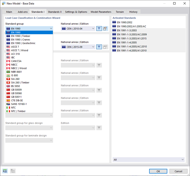
With Dlubal, you can safely and easily design structures all over the world. Select from a large number of standards in the Base Data. You can also decide whether to create the combinations automatically.
The following standards are available:
-
EN 1990
-
EN 1990 | Timber
-
EN 1990 | Road Bridges
-
EN 1990 | Cranes
-
EN 1990 | Geotechnical Engineering
-
EN 1990 | Base + Timber
-
EN 15512
-
ASCE 7
-
ASCE 7 | Timber
-
ACI 318
-
IBC
-
 CAN/CSA
 -
NBC
-
NBC | Timber
-
 NBR 8681
 -
 IS 800
 -
 SIA 260
 -
SIA 260 | Timber
-
 BS 5950
 -
GB 50009
-
GB 50068
-
GB 50011
-
CTE DB-SE
-
 SANS 10160-1
 -
 NTC
NTC -
NTC | Timber
-
 AS/NZS 1170.0
 -
 SP 20.13330:2016
 -
 TSC | Steel
For the European standards (EC), the following National Annexes are available:
-
 DIN | 2012-08 (Germany)
 -
CEN | 2010-04 (European Union)
-
 BDS | 2013-03 (Bulgaria)
 -
BS | 2009-06 (United Kingdom)
-
 CSN | 2015-05 (Czech Republic)
 -
 CYS | 2010-06 (Cyprus)
 -
 DK | 2013-09 (Denmark)
 -
 ELOT | 2009-01 (Greece)
 -
 EVS-EN 1990:2002+NA:2002 (Estonia)
 -
 IS | 2010-04 (Ireland)
 -
 LST | 2012-01 (Lithuania)
 -
 LU | 2020-03 (Luxembourg)
 -
 LVS | 2015-01 (Latvia)
 -
 MS | 2010-02 (Malaysia)
 -
 NBN | 2015-05 (Belgium)
 -
 NEN | 2011-12 (Netherlands)
 -
 NF | 2011-12 (France)
 -
 NP | 2009-12 (Portugal)
 -
 NS | 2016-05 (Norway)
 -
 ÖNORM | 2013-03 (Austria)
 -
 PN | 2010-09 (Poland)
 -
 SFS | 2010-09 (Finland)
 -
 SIST | 2010-08 (Slovenia)
 -
 SR | 2006-10 (Romania)
 -
 SS | 2008-06 (Singapore)
 -
 SS | 2019-01 (Sweden)
 -
 STN | 2010-01 (Slovakia)
 -
 TKP | 2011-11 (Belarus)
 -
UNE | 2010-07 (Spain)
-
 UNI | 2010-10 (Italy)
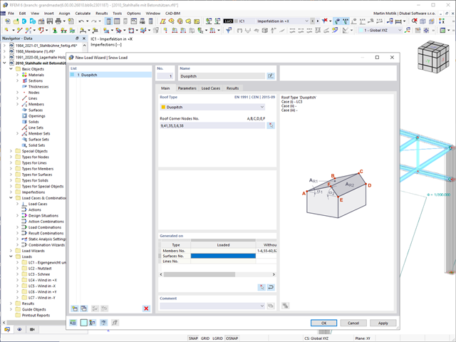
Do your structures also have to withstand snowfall? Use the Snow Load Wizard to generate snow loads as member loads or surface loads.
The following standards are available:
-
EN 1991-1-3 (incl. National Annexes)
-
ASCE 7
-
NBC
-
SIA 261
-
CTE DB-SE-AE
-
GB 50009
-
IS 875
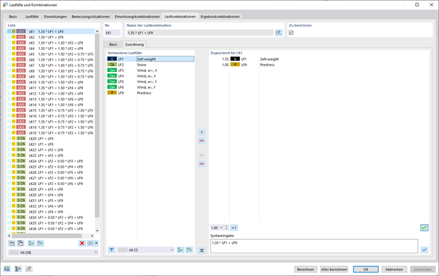
In the "Load Cases & Combinations" dialog box, you have an option to automatically generate load and result combinations as soon as you have selected the corresponding combination expressions. For example, you can also copy or add load cases in a clearly arranged window.
Furthermore, you can manage the load cases and combinations in the tables.
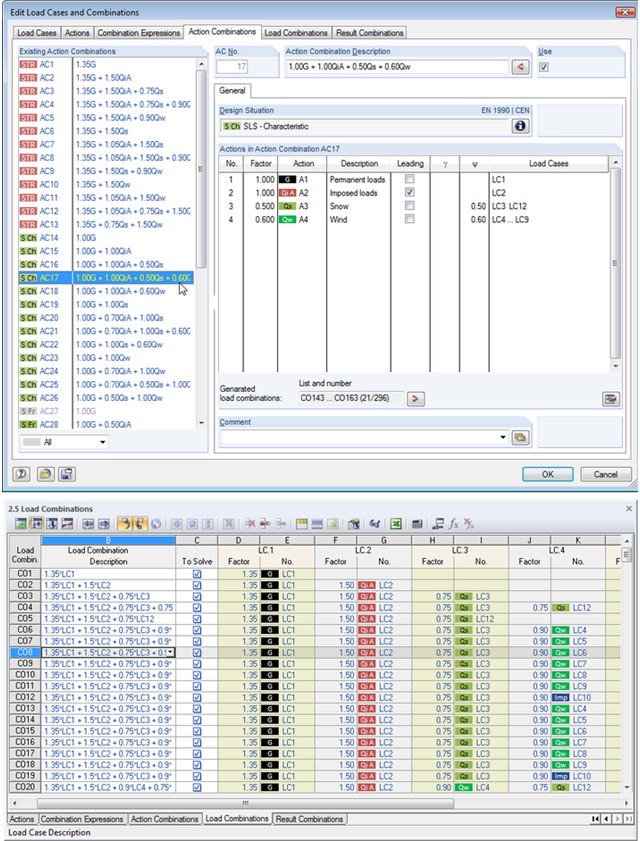
Utilize all the options of the 'Edit Load Cases and Combinations' dialog box to facilitate your work. Here you can automatically create load and result combinations after selecting the corresponding combination expressions. In this clearly arranged dialog box, you can also e.g. to copy, add, or renumber load cases.
Additionally, control the load cases and combinations in Tables 2.1 – 2.6.
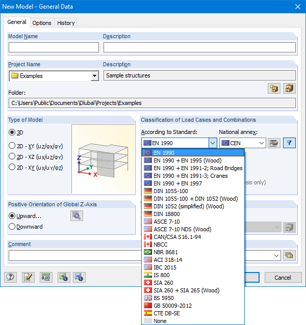
The Base Data dialog box includes a wide range of standards and the option to create combinations automatically. The following standards are available:
-
EN 1990:2002
-
EN 1990 + EN 1995:2004 (Timber)
-
EN 1990 + EN 1991-2; Road bridges
-
EN 1990 + EN 1991-3; Cranes
-
EN 1990 + EN 1997
-
to DIN 1055-100:2001-03
-
DIN 1055-100 + DIN 1052:2004-08 (timber)
-
DIN 1055-100 + DIN 18008 (Glass)
-
DIN 1052 (simplified) (timber)
-
DIN 18800:1990
-
ASCE 7‑10
-
ASCE 7-10 NDS (Wood)
-
ACI 318-14
-
IBC 2015
-
CAN/CSA S 16.1-94:1994
-
NBCC: 2005
-
NBR 8681
-
IS 800:2007
-
SIA 260:2003
-
SIA 260 + SIA 265:2003 (timber)
-
BS 5950-1:2000
-
GB 50009-2012
-
CTE DB-SE
For the European standards (EC), the following National Annexes are available:
-
DIN EN 1990/NA:2009-05 (Germany)
-
NBN EN 1990 - ANB: 2005 (Belgium)
-
BDS EN 1990:2003/NA:2008 (Bulgaria)
-
DK EN 1990/NA:2007-07 (Denmark)
-
SFS EN 1990/NA:2005 (Finland)
-
NF EN 1990/NA:2005/12 (France)
-
ELOT EN 1990:2009 (Greece)
-
UNI EN 1990/NA:2007-07 (Italy)
-
IS EN 1990:2002 + NA:2010 (Ireland)
-
LVS EN 1990:2003/NA:2010 (Latvia)
-
LST EN 1990/NA:2010-11 (Lithuania)
-
LU EN 1990/NA:2011-09 (Luxembourg)
-
MS EN 1990:2010 (Malaysia)
-
NEN EN 1990/NA:2006 (Netherlands)
- NS EN 1990/NA:2008 (Norway)
-
ÖNORM EN 1990:2007-02 (Austria)
-
NP EN 1990:2009 (Portugal)
-
PN EN 1990/NA:2004 (Poland)
-
SR EN 1990/NA:2006-10 (Romania)
-
SIST EN 1990: 2004/A1:2005 (Slovenia)
-
SS EN 1990:2008 (Singapore)
-
SS EN 1990/BFS 2010:28 (Sweden)
-
STN EN 1990/NA:2009-08 (Slovakia)
-
UNE EN 1990 2003 (Spain)
-
CSN EN 1990/NA:2004-03 (Czech Republic)
-
BS EN 1990/NA:2004-12 (the United Kingdom)
-
TKP EN 1990/NA:2011 (Belarus)
-
CYS EN 1990:2002 (Cyprus)
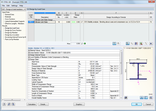
The first window shows the maximum design ratios including the corresponding design of each designed load case, load combination, or result combination.
The other result windows list all detailed results sorted by specific subject in extendable tree menus. All intermediate results along the members can be displayed at any location. In this way, you can easily retrace how the module has performed the individual designs.
The complete module data are part of the RFEM/RSTAB printout report. You can select the report contents and extent specifically for the individual designs.
It is necessary to enter material, load, and combination data in RFEM/RSTAB in compliance with the design concept specified by GB 50017. The RFEM/RSTAB material library already contains the relevant materials.
The RF-/STEEL GB add-on module requires members and sets of members, as well as load cases, load combinations, and result combinations to be designed.
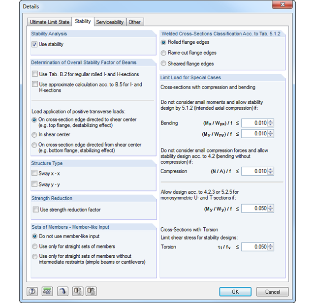
In the subsequent input windows, you can adjust preset definitions of lateral intermediate supports and effective lengths. This setting is then used by the program to determine the critical loads and moments required for the stability analysis in these situations.
- Design of tension, compression, bending, shear, and combined internal forces
- Stability analysis for flexural buckling and lateral-torsional buckling
- Automatic determination of critical buckling loads and overall stability factors for lateral-torsional buckling according to Annex B
- Optional application of discrete lateral supports to beams
- Automatic local stability analysis and check of plastic design criteria of a cross-section
- Deformation analysis (serviceability)
- Cross-section optimization
- Wide range of cross-sections available, such as rolled I-sections, channel sections, rectangular hollow sections, angles, T-sections. Welded sections: I-shaped (symmetrical and asymmetrical about major axis), channel sections (symmetrical about major axis), rectangular hollow sections (symmetrical and asymmetrical about major axis), angles, round pipes, and round bars
- Clearly arranged result tables
- Detailed result documentation including references to design equations of the used standard
- Various filter and sorting options of results, including result lists by member, cross-sections, x-location, or by load case, load and result combination
- Result table of member slenderness and governing internal forces
- Parts list with weight and solid specifications
- Seamless integration in RFEM/RSTAB
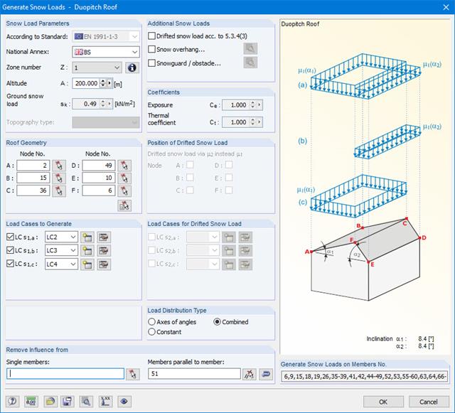
Snow loads can be generated as member loads on flat/monopitch roofs and duopitch roofs.
Additional snow loads such as drifted snow loads, snow overhangs, and snow guards can be taken into account as well.
The following standards are available:
-
EN 1991-1-3 (incl. National Annexes)
-
DIN 1055-5
-
CTE DB-SE-AE
-
ASCE/SEI 7-16
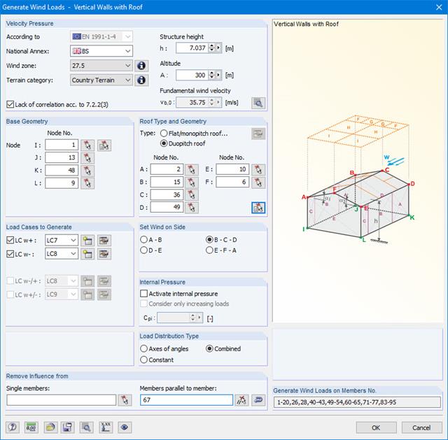
Wind loads can be automatically generated as member loads on the following structural components (optional with internal pressure for open buildings):
- Vertical walls
- Flat roofs
- Monopitch roofs
- Duopitch/troughed roofs
- Vertical walls with roof
The following standards are available:
-
EN 1991-1-3 (incl. National Annexes)
-
DIN 1055-4
-
CTE DB-SE-AE
-
ASCE/SEI 7-16
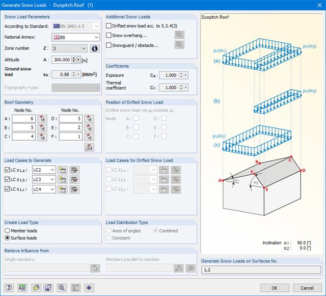
The snow load generator can generate snow loads as member loads or surface loads.
Additional snow loads such as drifted snow loads, snow overhangs, and snow guards can be taken into account as well.
The following standards are available:
-
EN 1991-1-3 (incl. National Annexes)
-
DIN 1055-5
-
CTE DB-SE-AE
-
ASCE/SEI 7-16

Wind loads can be automatically generated as member loads or area loads on the following structural components (optional with internal pressure for open buildings):
- Vertical walls
- Flat roofs
- Monopitch roofs
- Duopitch/troughed roofs
- Vertical walls with roof
The following standards are available:
-
EN 1991-1-3 (incl. National Annexes)
-
DIN 1055-4
-
CTE DB-SE-AE
-
ASCE/SEI 7-16