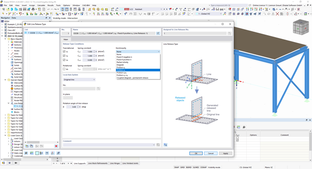
You can simulate the static friction effects between two supporting components along a line using the "Friction" nonlinearity in the Line Release Type.
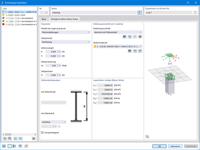
If you are working with nonlinearities, this feature is suited very well to support you. For example, you can specify nonlinearities of member end releases (yielding, tearing, slippage, and so on) and supports (including friction). Furthermore, you can use special dialog boxes to determine the spring stiffnesses of columns and walls based on the geometry specifications.

- Nonlinear member types, such as tension and compression members or cables
- Member nonlinearities, such as failure, tearing, yielding under tension or compression
- Support nonlinearities, such as failure, friction, diagram, and partial activity
- Release nonlinearities, such as friction, partial activity, diagram, and fixed if positive or negative internal forces
The nonlinear calculation adopts the real mesh geometry of planar, buckled, simple curved, or double curved surface components from the selected cutting pattern and flattens this surface component in compliance with the minimization of distortion energy, assuming defined material behavior.
In simplified terms, this method attempts to compress the mesh geometry in a press, assuming frictionless contact, and to find the state in which the stresses from flattening in the component are in equilibrium in the plane. This way, minimum energy and optimum accuracy of the cutting pattern are achieved. Compensation for warp and weft as well as compensation for boundary lines are considered. Then, the defined allowances on boundary lines are applied to the resulting planar surface geometry.
Features:
- Minimization of distortion energy in the flattening process for very accurate cutting patterns
- Application for almost all mesh arrangements
- Recognition of adjacent cutting pattern definitions to keep the same length
- Mesh application for main calculation
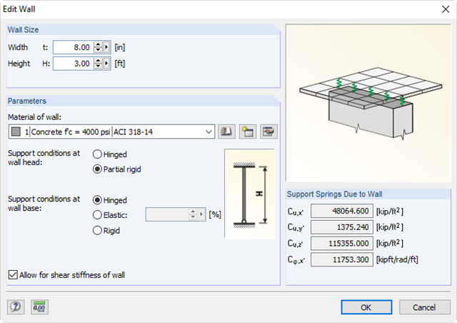
It is possible to specify nonlinearities of member end releases (yielding, tearing, slippage, and so on) and supports (including friction). There are special dialog boxes available for determining the spring stiffnesses of columns and walls based on the geometry specifications.
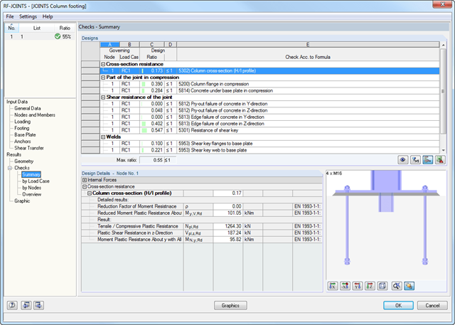
After the calculation, RF-/JOINTS Steel - Column Base displays the following design results:
- Base plate bending
- Anchor tension and anchor shear force
- Shear key strength
- Concrete compression / failure of concrete edges
- Friction
- Welds
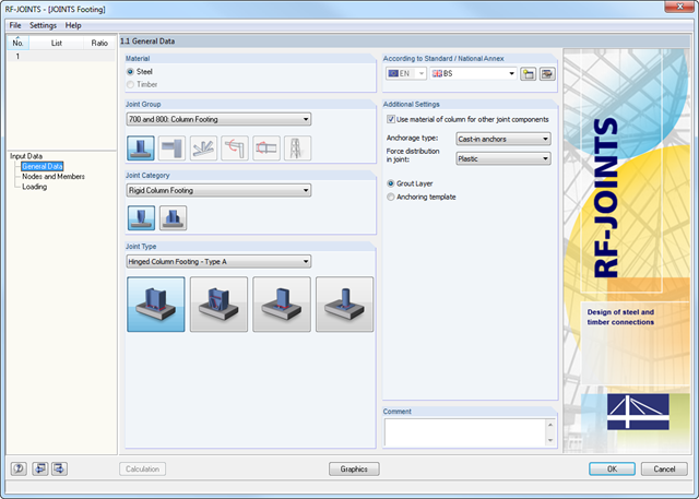
The Hinged Column Footing category provides four different base plate connections:
- Simple column base
- Tapered column base
- Column base for rectangular hollow sections
- Column base for circular hollow sections
The Restraint Column Footing category provides five different joint layouts of I-sections:
- Base plate without stiffening
- Base plate with stiffeners in center of flanges
- Base plate with stiffeners on both sides of column
- Base plate with channel sections
- Pocket foundation
All connection types include a base plate welded around a steel column. Connections with anchors are set in concrete within the foundation. You can select anchor types M12 – M42 with steel grades of 4.6 – 10.9. The top and bottom sides of the anchors can be provided with round or angled sheets for better load distribution or anchorage. In addition, you can use rectangular or circular anchor heads with threads applied at the member ends.
The material and thickness of the grout layer, as well as the dimensions and material of the footing, can be set freely. Furthermore, you can define edge reinforcement of the footing. For a better transfer of shear forces, it is possible to arrange a shear key (cleat) on the bottom side of the base plate.
Shear forces are transferred by a cleat, anchors, or friction. You can combine the individual components.