The structural analysis software RFEM 6 is the basis of a modular software system. The main program RFEM 6 is used to define structures, materials, and loads of planar and spatial structural systems consisting of plates, walls, shells, and members. The program also allows you to create combined structures as well as to model solid and contact elements.
RSTAB 9 is a powerful analysis and design software for 3D beam, frame, or truss structure calculations, reflecting the current state of the art and helping structural engineers meet requirements in modern civil engineering.
Do you often spend too long calculating cross-sections? Dlubal Software and the RSECTION stand-alone program facilitate your work by determining section properties of various cross-sections and performing a subsequent stress analysis.
Do you always know where the wind is blowing from? From the direction of innovation, of course! With RWIND 2, you have a program at your side that uses a digital wind tunnel for the numerical simulation of wind flows. The program simulates these flows around any building geometry and determines the wind loads on the surfaces.
Are you looking for an overview of snow load zones, wind zones, and seismic zones? Then you are in the right place. Use the Geo-Zone Tool to determine quickly and efficiently snow loads, wind speeds, and seismic data according to ASCE 7‑16 and other international standards.
Would you like to try out the capabilities of the Dlubal Software programs? You have the opportunity to do so! The free 90-day full version allows you to thoroughly test all our programs.
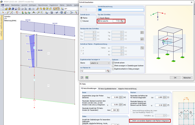
If the section was defined on an unused line, activate the "Integrate unutilized objects into surfaces" check box in FE Mesh Settings. There is a section defined on Line 7 and Line 12 in Image 01. Line 7 has no other function for Surface 1. It is not the boundary line of Surface 1, nor does it have a support or a load. In FE Mesh Settings, the "Integrate unutilized objects into surfaces" check box is deactivated so that no result diagrams are displayed on Line 7. On the other hand, Line 12 is subjected to a load, so the result diagrams are displayed on this line. When selecting the "Integrate unutilized objects into surfaces" checkbox, the result diagrams are also displayed on Line 7.
If the section runs through several surfaces, the respective surfaces have to be specified in the "On Surface No." section. Image 02 shows a section through Surface 3 and Surface 4. In the "On Surfaces No." section, only Surface No. 3 is specified, so that result diagrams are also only displayed on this surface. Surface 4 would have to be specified in the "On Surfaces No." section in order to display the result diagrams here as well.
Materials are required to define surfaces, cross-sections, and solids. The material properties affect the stiffnesses of these objects.
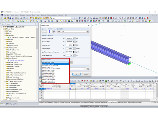
There are 13 material models available if you have a license for the RF‑MAT NL add-on module.
In the case of the abundance of material models, it is necessary to make sure that you assign the corresponding material model to the members and their surfaces/solids.
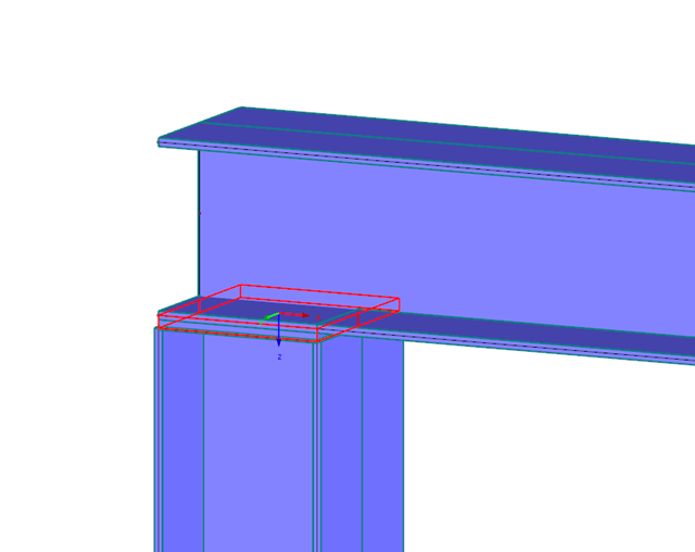
In the example shown here, surfaces have been generated from a member for a detailed analysis. There is still an unused cross-section defined (marked in blue) and the material is entered for the member cross-section as well as for the surfaces. When editing an existing material to Isotropic Nonlinear Elastic 2D/3D, the 2D/3D material model is also defined for the created member cross-section, which leads to the error message.
When working with members and surfaces / solids, we recommend creating more than one material.
In order to generate the FE mesh, it is necessary to meet the following conditions in this case:
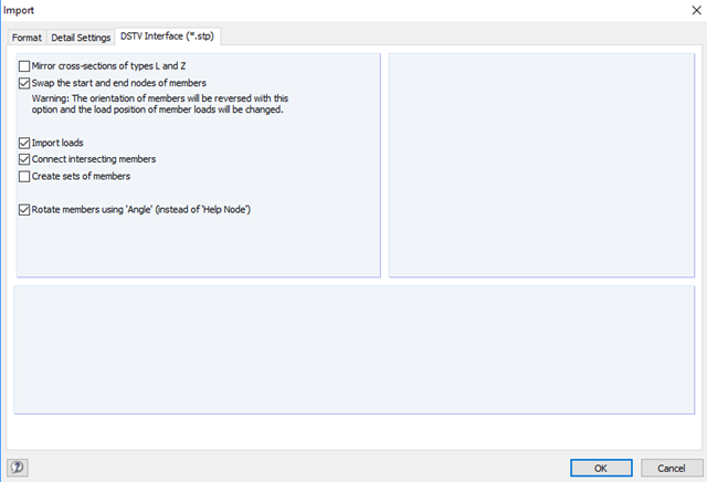
This problem cannot always be avoided when importing DXF drawings.
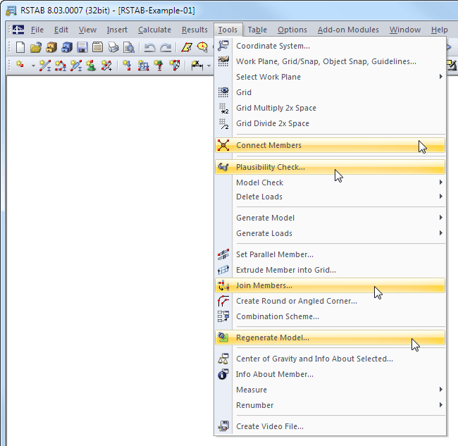
In addition to the plausibility check, other functions are available in the Tools menu for eliminating duplicate coordinates:
Connect Members
This function allows you to draw a window over an area. If the members should intersect with nodes there, they are automatically divided.
Join Members
You can define an area around a node or a member and connect the nodes located in a certain radius to these nodes eccentrically or by moving them.
Model Check → Identical Nodes
This allows you to select duplicate nodes. You can define whether to delete the unused nodes or to merge the identical nodes.
Regenerate Model
Node coordinates with many decimal places resulting from the import can be rounded.
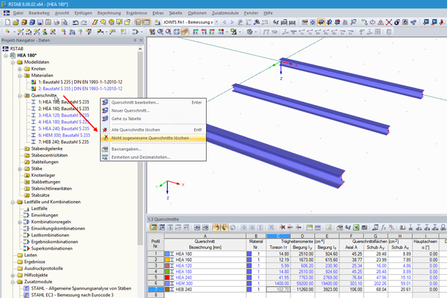
You can right-click the "Cross-Sections" entry in the Data navigator. A shortcut menu appears where you can find the "Delete Unassigned Cross-Sections" command, which allows you to delete the cross-sections that are currently not used in the model (blue font) with just one click.
This procedure also works for materials, member hinges, and so on.