The structural analysis software RFEM 6 is the basis of a modular software system. The main program RFEM 6 is used to define structures, materials, and loads of planar and spatial structural systems consisting of plates, walls, shells, and members. The program also allows you to create combined structures as well as to model solid and contact elements.
RSTAB 9 is a powerful analysis and design software for 3D beam, frame, or truss structure calculations, reflecting the current state of the art and helping structural engineers meet requirements in modern civil engineering.
Do you often spend too long calculating cross-sections? Dlubal Software and the RSECTION stand-alone program facilitate your work by determining section properties of various cross-sections and performing a subsequent stress analysis.
Do you always know where the wind is blowing from? From the direction of innovation, of course! With RWIND 2, you have a program at your side that uses a digital wind tunnel for the numerical simulation of wind flows. The program simulates these flows around any building geometry and determines the wind loads on the surfaces.
Are you looking for an overview of snow load zones, wind zones, and seismic zones? Then you are in the right place. Use the Geo-Zone Tool to determine quickly and efficiently snow loads, wind speeds, and seismic data according to ASCE 7‑16 and other international standards.
Would you like to try out the capabilities of the Dlubal Software programs? You have the opportunity to do so! The free 90-day full version allows you to thoroughly test all our programs.
The "Auto Hide" setting may be active. In this case, please move the mouse over the strip visible on the edge of the window. The tables (or the navigator) should then be displayed again. If this does not solve the problem, you can restore the default settings. Please proceed as follows:
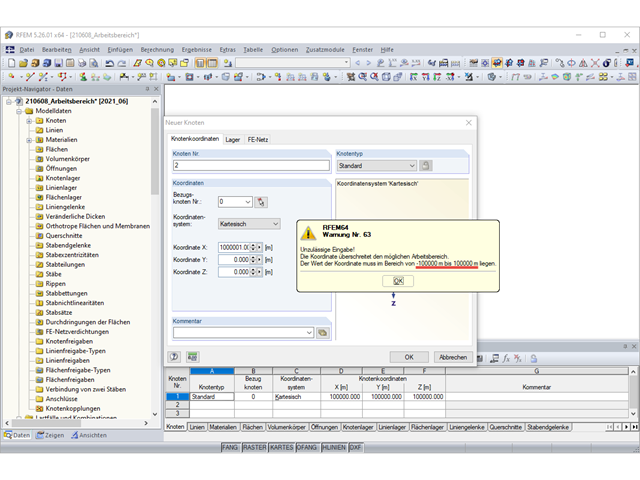
The value of the coordinates must lie in the range from -100,000 m to 100,000 m.
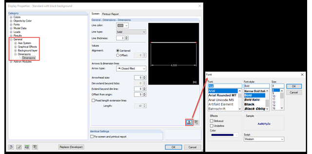
You can change the font size for dimensions under Display Properties.
You can access it using the menu "Options" → "Display Properties" → "Edit" or via the shortcut menu (right-click in the free workspace).
Under the "General" → "Dimensions" → "Dimensions" tab, you can then "Set Fonts" for the dimensions.
Further settings for dimensions, a line type, a line thickness, and color can be found in the same tab.
Note
If you have made several changes in this way, but do not want to use them all the time, you can create and save different configurations in the Configuration Manager. These configurations contain, among other things, the display properties.
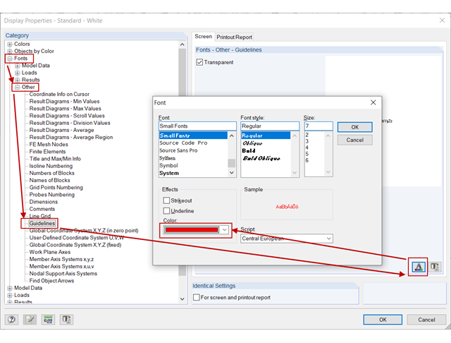
The font color of the guideline numbering can be changed in Display Properties:
Right-click the workspace → Display Properties → Fonts → Other → Guidelines → "Font" button → Change Color; see the image.
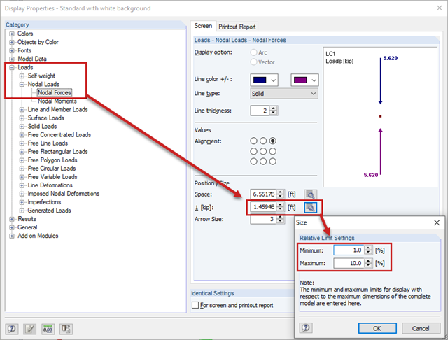
This adjustment of the arrow sizes of punching loads can be done in the display properties in the main program: Shortcut menu (right-click the workspace) → Display Properties → Loads → Nodal Loads → Nodal Forces; see the image.
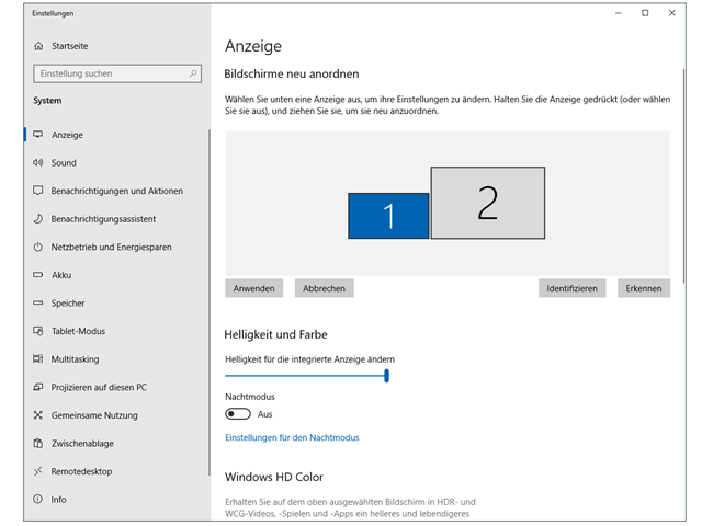
If you use two or more monitors, you can, for example, move the project navigator, tables, the add-on module windows, or a printout report to the other display. This way, you can easily enlarge the workspace of the model.
By clicking the link below, you can find instructions on how to customize the elements of the user interface.
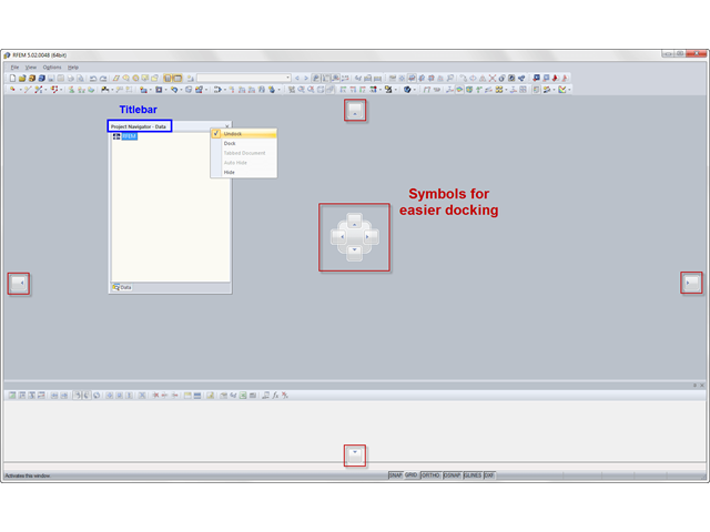
The navigator is similar to a toolbar: You can use the mouse to "grab" the navigator in its title bar and move it to the workspace. To dock it, double-click the title bar or move the navigator to the window frame.
When moving the navigator, symbols appear that facilitate the docking to one of the four sides of the work window:
If the navigator is undocked, you can change its size by "dragging" the edges.