11 Results
View results:
Sort by:

Surfaces in building models can be of many different sizes and shapes. All surfaces can be considered in RFEM 6 because the program allows to define different materials and thicknesses as well as surfaces with different stiffness and geometry types. This article focuses on four of these surface types: rotated, trimmed, without thickness, and load transfer.
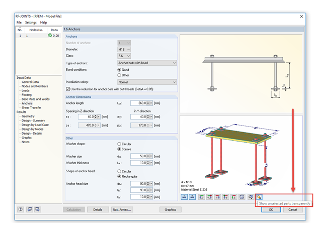
The RF‑/JOINTS add‑on modules are equipped with a graphical window that shows all the structural components of the connection. There, you can use the mouse functions known from RFEM and RSTAB to zoom, move, or rotate the view.

Nodal supports are usually defined with regard to the global axis system. However, it is sometimes necessary to rotate the nodal support. For example, for a floor slab with a pile foundation. For geological reasons, the piles do not rest in the ground vertically, but in an inclined position. Each end point of the piles has a nodal support that can only absorb forces along the pile foundation direction. Therefore, rotating the nodal support is required. Various options for this are described in previous posts.

If you want to connect members tangentially to a curved member or a curved surface in RFEM, it is necessary to define the member rotation of the connected members. In order to avoid manual determination, you can display the center point of the curved line and place a node on it. Then, you can select the "Member Rotation via Help node" option and specify the relevant help nodes. Thus, the members are rotated automatically in the defined plane (x-z in our example) and the top edge of the rotated cross-section is parallel to the tangent of the curved line.
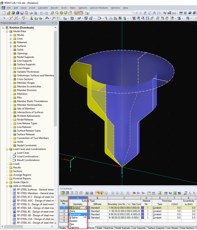
You can quickly model very complex objects in RFEM by rotating lines or polylines. If you need to change the model subsequently, quadrangle surfaces provide an advantage, as they include editable boundary lines.
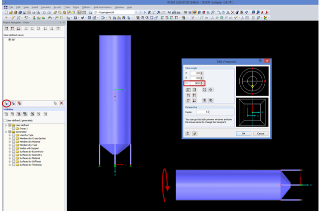
If you consider rotating the structure shown in the figure around the global Y‑axis, this might be not straightforward. In order to achieve better handling, the axis is always locked in the direction of your view. In the case of very high structures, it may be helpful to rotate the view about 90 degrees in the viewing direction.
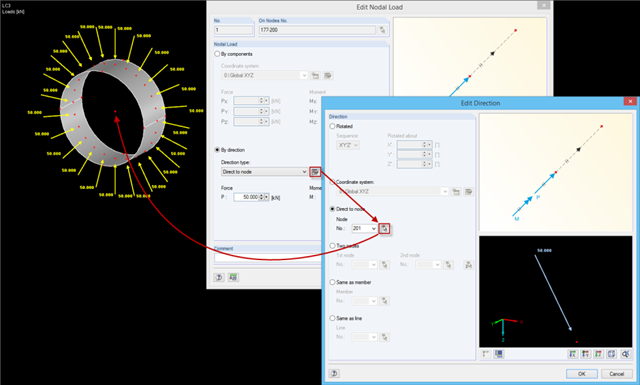
When defining nodal loads, you can rotate the load using several simple options: ~ Rotation by angle around the global coordinate axes in a specific order, ~ Alignment with a user-defined coordinate system, ~ Direction to a particular node, ~ Alignment by means of two nodes, ~ In the direction of a member/line.
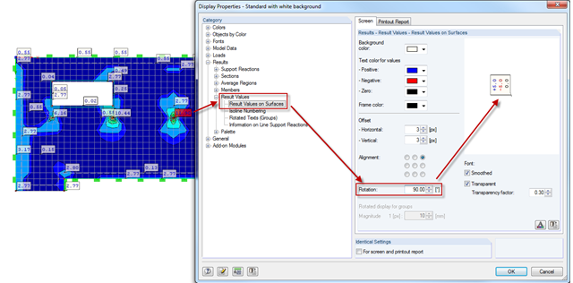
Sometimes, it is necessary to rotate graphics in the printout report. In order to also display the result values correctly, you can rotate the results by the respective angle using the Display Properties dialog box. As usual in Display Properties, this setting is to be done separately for the screen view and the printout report.
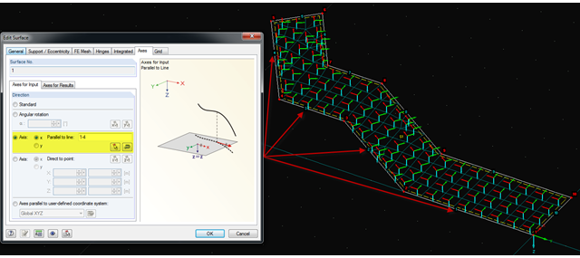
It is often necessary to adjust the FE mesh of surface elements to the geometric structure. RFEM provides various options for this. For example, the FE axis can be rotated around a point, aligned in the direction of a point, or oriented to a user-defined coordinate system. Another option is the direction parallel to a line, and in this case in particular, it is possible to enter or select several lines.
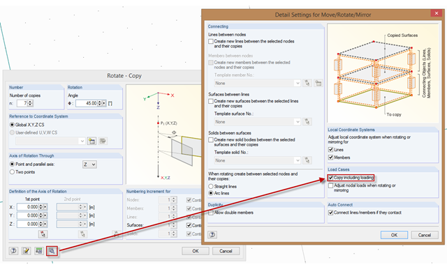
In order to also consider loading when copying, mirroring, or rotating, the corresponding option must be activated. To do this, select the corresponding check box in the "Detail Settings for Move/Rotate/Mirror" dialog box. Then, loading is included when copying until you deactivate this function.
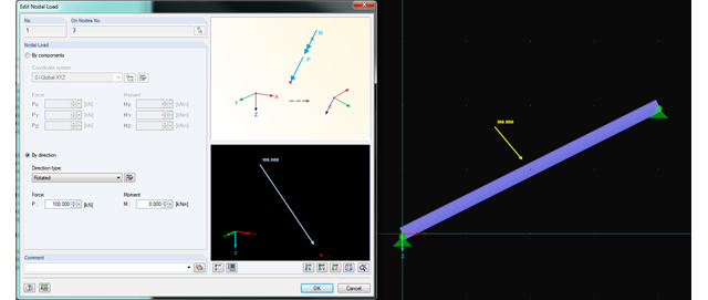
In RFEM and RSTAB, you can now rotate nodal loads or apply them on member axes. Thus, inclined members can also be loaded with nodal loads perpendicularly or along the member axis.