Surfaces in construction can be found in myriad sizes and shapes, from simple planes like walls, ceilings, or slabs, to single-curved cylinders like silos, to multi-curved membrane structures. The stiffness of a surface results from its material and thickness.
For the structural analysis and FE mesh generation, 2D elements are generated on the surfaces, which are applied in their centroidal axis for the calculation. In this way, deformations as well as internal forces and moments can be determined, which can then be designed in accordance with the material and standards.
All of the above structures can be considered in RFEM 6 because the program allows you to define surfaces with different stiffnesses, geometries, materials, and thicknesses. Surfaces are available as “Basic Objects” in the Data Navigator (Image 1). Double-clicking on the entry opens a new window in which you can define the surface of interest.
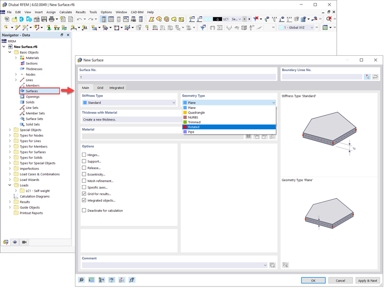
The “Main” tab of the “New Surface” window shown in Image 1 allows you to define the basic surface parameters. Two of these parameters are surface type and surface stiffness, which are also the focus of this article. In this way you can define surfaces of different geometries:
- Plane
- Quadrangle
- NURBS
- Trimmed
- Rotated
- Pipe
For the stiffness type, on the other hand, you can choose among the following:
- Standard
- Without Thickness
- Rigid
- Membrane
- Without Membrane Tension
- Load Transfer
As mentioned earlier, you can use these options to describe and later design any planar or curved surface you might find in a building model. Each of the types listed above will be explained in upcoming articles, while this specific text will give you a more detailed insight into the rotated, trimmed, without thickness, and load transfer surface types in RFEM 6.
Surface Type “Rotated”
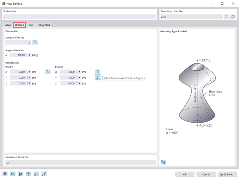
If you are interested in modeling domes, circular walls, or silos, and storage tanks, this is the surface type you need to know about. In general, the rotated surface is created by revolving a line around a fixed axis. When generating a rotated surface in RFEM 6, the same logic applies: boundary line, axis of rotation, and angle of rotation must be defined. Hence, when you select the “Rotated” surface type in the “Main” tab of the “New Surface” window, a new tab will appear where you can define these parameters (Image 2).
As shown in the image, the axis of rotation can be defined by selecting two points (that is, P and R). You can write the coordinates of these points directly in the dialog box or select them individually in graphics. There is also the possibility to select both points at once using the “Select Rotation Axis Points in Graphics” option.
If you have already defined the material, thickness, and stiffness of the surface in the “Main” tab of the “New Surface” window, the program creates the surface from the start and end position of the line and the rotation of the line definition points. As already mentioned, this makes it very easy to create not only components but entire models in a very simple and fast manner.
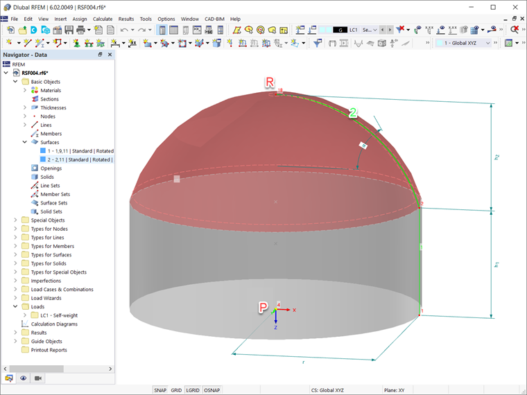
An example of this is the modeling of the dome and circular wall shown in Image 3. Both surfaces are created by a "Rotated" geometry type. To better understand the parameters used for creating this type of surface, the image shows the boundary line (line No. 2) and the axis of rotation (represented by nodes P and R) of the surface representing the dome. This surface is created by rotating the boundary line around the axis of rotation for the angle of rotation α=360°.
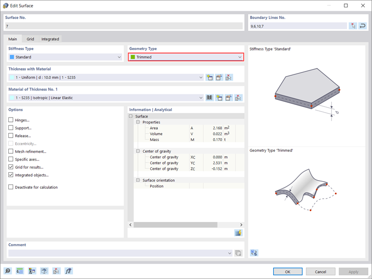
Surface Type “Trimmed”
The trimmed surface is related to a new feature in RFEM 6 that allows the intersection of curved surfaces and solids. By creating the intersection, the program generates surfaces of the "Trimmed" surface type. You can use this feature to create very complex geometries, such as pipe intersections or curved openings, in a simple and fast manner.
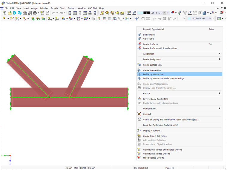
For example, look at the model shown in Image 5. There are three pipes for which an intersection is to be created. To do this, first select them as shown in the image. Then use the “Divide by Intersection” function available in the shortcut menu of the selected objects.
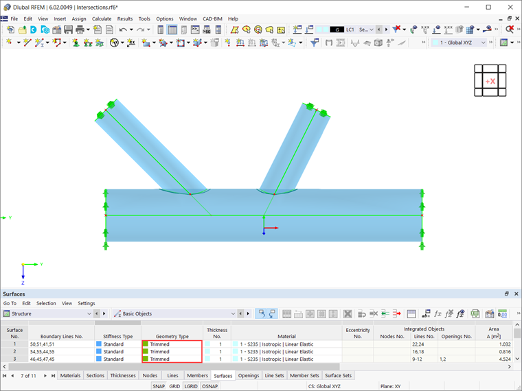
With this function, the initial surfaces are divided at the intersection lines, and openings are automatically created at the cutting surfaces. This creates new surfaces that can be edited or deleted as independent objects. In this way, you can delete the unnecessary surfaces and get the pipe intersection as shown in Image 6. As shown in the image, the surfaces are now of the "Trimmed" type.
This is just an example of using the “Divide by Intersection” function and the “Trimmed” surface type. As mentioned earlier, you can create many other complex curved surfaces or perforated bodies with this simple process.
Surface Type “Without Thickness”
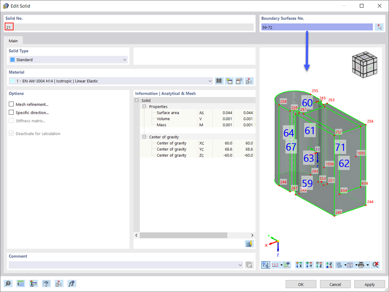
These surfaces are needed for the definition of solids. The surface has no stiffness and is intended to be used as the boundary surface of a solid. However, surfaces with the “Without Thickness” stiffness type can still be configured by different geometry types (for example, planar, quadrilateral, trimmed, and so on). An example of such surfaces is shown in Image 7.
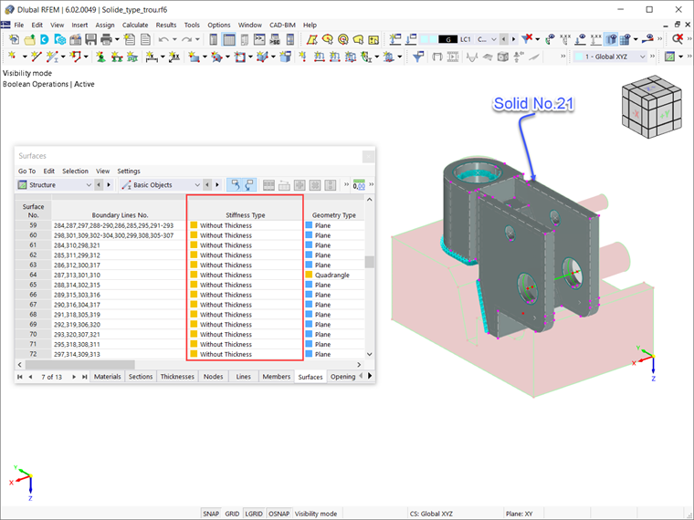
The “Surfaces” table in Image 7 shows that surfaces Nos. 59-72 are of the “Without Thickness” stiffness type. This is because they are boundary surfaces of Solid No. 21, as shown in Image 8.
Surface Type “Load Transfer”
In addition to the load wizards, which make it easier to enter loads, RFEM 6 offers the new surface type "Load Transfer" for even easier load application. Thus, by creating a surface of this stiffness type, the program creates a new surface with no thickness and no structural effect, but with a unique ability to transfer loads.
This is an advantageous feature in RFEM 6, which enables the consideration of loads from surfaces that are not included in the model itself (for example, facade structures, glass surfaces, trapezoidal roof sections, and so on).
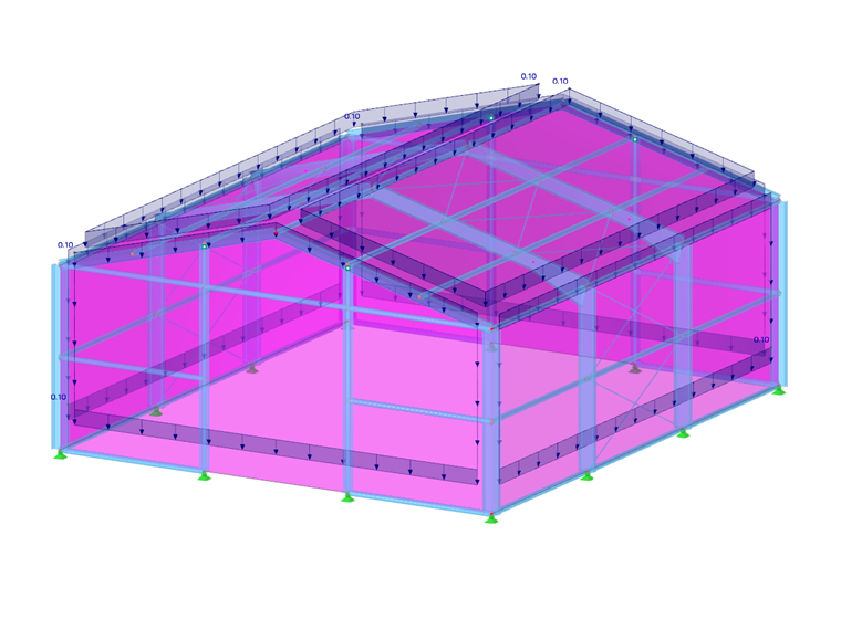
An example is shown in Image 9, where surface No. 18 is created with the “Load Transfer” stiffness type to account for wind loads on the unmodeled façade wall of the structure.
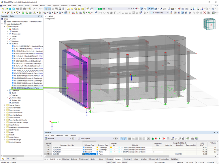
As shown in the example, you can use load transfer surfaces to apply area loads to areas that are not directly modeled as surfaces. The load on this surface is distributed to the edges or the integrated objects. If member loads are generated, the load is converted into the global directions based on the true member lengths (load directions XL, YL, ZL).
In contrast to the load wizards, where the load area has to be redefined each time, a load transfer surface can be used several times for different load applications. More specifically, this approach allows different surface loads to be assigned by using a single load transfer surface. To learn more about this type of surface and how to define its parameters, see this Knowledge Base article: Using Load Transfer Surface in RFEM 6 .