


The mesh settings can be controlled in a specific dialog box where the data are organized in several tabs.
General
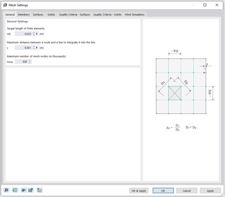
The Target length of finite elements controls the global size of the mesh. The finer the mesh size, the more precise the results will be. However, it also increases the the amount of data and the computation time, as for every additional FE node, more equations must be solved. In addition, singularity effects are more noticeable with a fine mesh.
The discretization is a crucial point for the subsequent FE analysis: A mesh size that is too fine will delay the calculation without significantly increasing the quality of the results. If, on the other hand, the mesh size is too coarse, the boundary conditions are captured insufficiently. As orientation for the desired side length of the finite elements is the following recommendation: About about eight to ten elements should be generated between the boundary lines of a surface. A minimum number of four elements should be met.
The Maximum distance between a node and a line controls the permissible distance for a node from a line to be integrated into its FE mesh. If the distance from the node is larger, a new FE mesh node will be created for it.
The Maximum number of mesh nodes controls the limit of generated nodes so that the efficiency of the program and computer is guaranteed.
Members
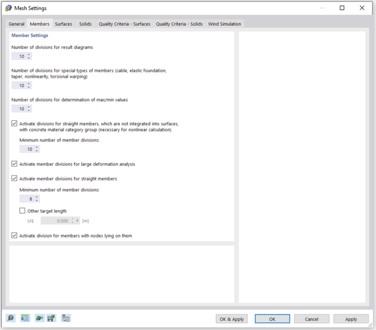
The Number of divisions for special types of members – such as cables, tapers, or members with elastic foundations or nonlinear features – can be adjusted appropriately so that real divisions of the members are made by intermediate nodes. However, this specification has no effect if a member is arranged at the boundary line of a surface or if a mesh refinement is applied to its definition line.
With the option Activate member divisions for large deformation analysis, beams can be divided by intermediate nodes for that type of calculation that requires a higher accuracy. The number of member divisions is taken from the one defined for the "special types of members".
If you use the option Activate member divisions for straight members which are not integrated in surfaces, FE nodes will be created at all free members and taken into account accordingly in the calculation. The FE length is either taken from the global mesh size (LFE) of the General tab or can be defined manually.
With the option Activate division for members with nodes lying on them, FE nodes are generated at the locations of the member where other members end, but have no connection to it.
Surfaces
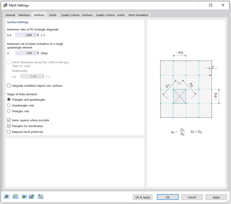
The most accurate results are obtained for elements that are as close as possible to a square. For a square, the ratio of the diagonals D1/D2 = 1. This is visualized on the right side of the tab. The Maximum ratio of FE rectangle diagonals controls the limit value ΔD of the ratio between the two diagonals. However, the specified ratio is not compulsory when the value cannot be kept to optimally create adjoining elements. If the value is too large, however, elements with very acute or obtuse angles may be created, which can lead to numerical problems.
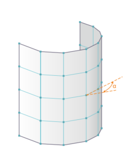
A curved surface is covered by plane elements when forming the FE mesh. The Maximum out-of-plane inclination angle α defines the limit inclination of a single quadrangle element from the plane. It describes the largest permissible angle between the normals of two elements (see the following figure with the normals of two triangular elements). If the value is exceeded, the element will be divided in further triangular elements.
The Shape of finite elements consists of both triangular and quadrangular elements by default. This is based on the following consideration: A mesh consisting only of squares is often not possible, though it would produce the most accurate results. Triangles, on the other hand, can mesh any surface, but tend toward "locking"; that is, a small numerical error. Therefore, triangles are used for difficult areas, but squares or rectangles in general are preferred. Forcing one of the two element types exclusively is usually not useful.
Solids
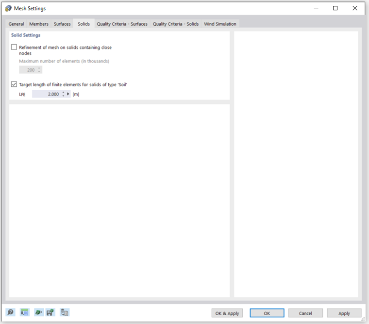
If nodes are very close to each other on a solid, an automatic Refinement of mesh on solids can be activated. This will ensure that all nodes are correctly detected by the FE mesh. The mesh size of the solid results from the smallest distance between the nodes. The number of generated 3D elements can be limited manually for that option.
Furthermore, it is possible to define the Target length of finite element for solids of type 'Soil'. However, this value is not mandatory for the program. If the setting for an element cannot be reached, the next best variant will be generated.
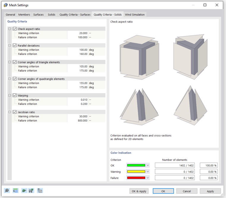
Quality Criteria - Surfaces / Quality Criteria - Solids
The parameters of the two "Quality Criteria" tabs make it possible to evaluate the results of the automatic FE mesh generation for surface and solid elements.
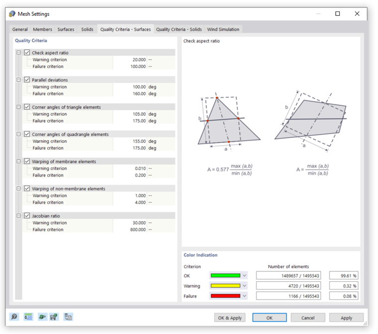
Several evaluation criteria are available where the limits can be each set for Warning and Failure. If any (activated) criterion is violated, the respective finite element will be marked. All elements are evaluated individually. The evaluation of the meshing is displayed in the lower right area of the tab. To display the critical elements graphically on the model, select the "Navigator - Display" where you then activate the Mesh Quality option in the Mesh category item.
For every quality criterion, the parameters of the selected criterion are shown on the right-hand side. In the image above, the "aspect ratio" option is illustrated.
The limits for marking the element can be set individually. Usually, it is advisable to leave the default values activated for all criteria. Depending on the application, it may be useful to make the criteria stricter or less strict.
The function offers a customizable and clear possibility to check the quality of the FE mesh and to adjust it, if necessary.
The same applies to the quality criteria for solid elements.
Wind Simulation
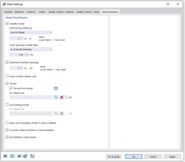
Specific mesh settings can also all be made for the "Wind Simulation" special solution add-on. If the RWIND program was purchased and used for wind tunnel simulations, it is generally recommended to make all settings directly in that program. In contrast to the settings defined in RFEM, the effects on the mesh can be evaluated directly there.
A detailed description of the wind simulation mesh settings can be found in the chapter FE Mesh of the RWIND manual.