
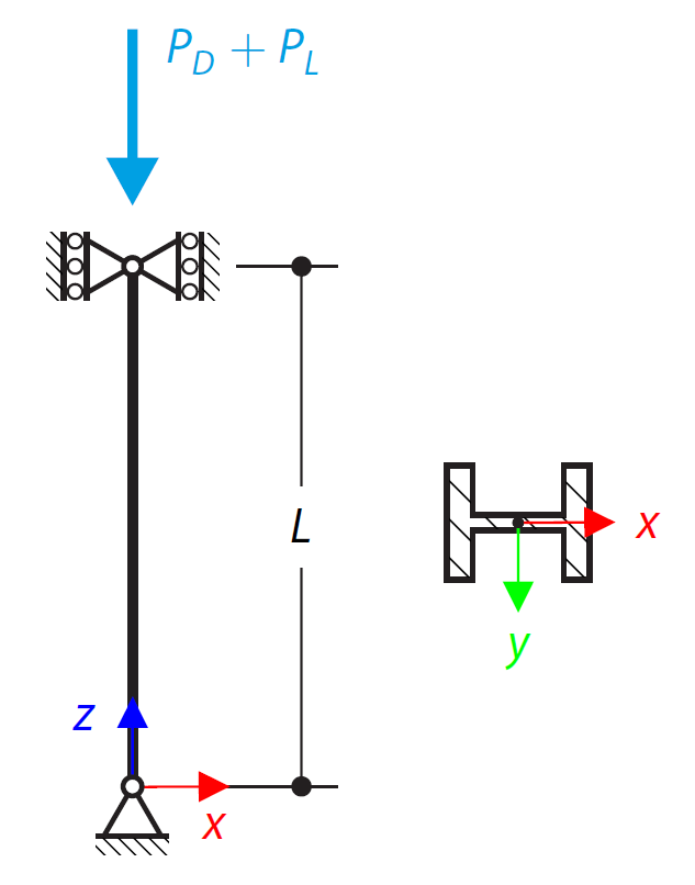
This example compares the effective lengths and critical load factor, which can be calculated in RFEM 6 using the Structure Stability add-on, with a manual calculation. The structural system is a rigid frame with two additional hinged columns. This column is loaded by vertical concentrated loads.

In this verification example, the capacity design values of shear forces on beams are calculated in accordance with EN 1998-1, 5.4.2.2 and 5.5.2.1 as well as the capacity design values of columns in flexure in accordance with 5.2.3.3(2). The system consists of a two span reinforced concrete beam with a span length of 5.50m. The beam is part of a frame system. The results obtained are compared with those in [1].

An inner column in the first floor of a three-story building is designed. The column is monolithic connected with the top and bottom beams. The fire design simplified method A for columns according to EC2-1-2 is than proofed and the results compared to [1].

The model is based on the example 4 of [1]: Point-supported slab.
The flat slab of an office building with crack-sensitive lightweight walls is to be designed. Inner, border and corner panels are to be investigated. The columns and the flat slab are monolithically joined. The edge and corner columns are placed flush with the edge of the slab. The axes of the columns form a square grid. It is a rigid system (building stiffened with shear walls).
The office building has 5 floors with a floor height of 3.000 m. The environmental conditions to be assumed are defined as "closed interior spaces". There are predominantly static actions.
The focus of this example is to determine the slab moments and the required reinforcement above the columns under full load.
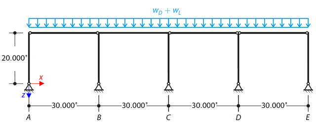
Determine the required strengths and effective length factors for the ASTM A992 material columns in the moment frame shown in Figure 1 for the maximum gravity load combination, using LRFD and ASD.
An ASTM A992 14×132 W-shaped column is loaded with the given axial compression forces. The column is pinned top and bottom in both axes. Determine whether the column is adequate to support the loading shown in Figure 1 based on LRFD and ASD.
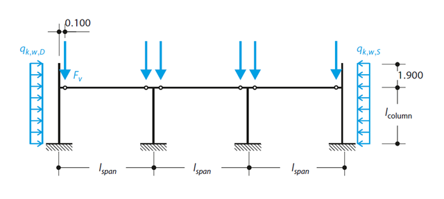
A reinforced concrete column is designed for ULS at normal temperature according to DIN EN 1992-1-1/NA/A1:2015, based on 1990-1-1/NA/A1:2012-08. The design employs the nominal curvature method; see DIN EN 1992-1-1, Section 5.8.8. The addressed column is located at the edge of a 3-span frame structure, which consists of 4 cantilever columns and 3 individual trusses hinged to them. The column is subjected to the vertical force of the precast truss, snow and wind. The results are compared with the literature.
Determine the required strengths and effective length factors for the ASTM A992 material columns in the moment frame shown in Figure 1 for the maximum gravity load combination, using LRFD and ASD.

A column is composed of a concrete section (rectangle 100/200) and a steel section (profile I 200). It is subjected to pressure force. Determine the critical load and corresponding load factor. The theoretical solution is based on the buckling of a simple beam. In this case, two regions have to be taken into account due to different moments of inertia and material properties.
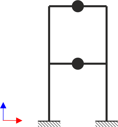
A two‑story, single‑bay frame structure is subjected to earthquake loading. The modulus of elasticity and cross‑section of the frame beams are much larger than those of the columns, so the beams can be considered rigid. The elastic response spectrum is given by the standard SIA 261/1:2003. Neglecting self-weight and assuming the lumped masses are at the floor levels, determine the natural frequencies of the structure. For each frequency obtained, specify the standardized displacements of the floors as well as equivalent forces generated using the elastic response spectrum according to the standard SIA 261/1.2003.
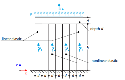
Four columns are fixed at the bottom and connected by a rigid block at the top. The block is loaded by pressure and modeled by an elastic material with a high modulus of elasticity. The outer columns are modeled by linear elastic material and the inner columns by a stress-strain diagram with decaying dependence. Assuming only the small deformation theory and neglecting the structure's self-weight, determine its maximum deflection.
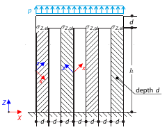
Determine the maximum deflection of four columns fixed at the bottom and connected by a rigid block at the top. The block is loaded by pressure and modeled by an elastic material with a high modulus of elasticity. The outer columns are modeled as orthotropic elastic material, and the inner columns as orthotropic elastic-plastic material with the same elastic parameters as the outer columns and plasticity properties defined according to the Tsai-Wu plasticity theory.