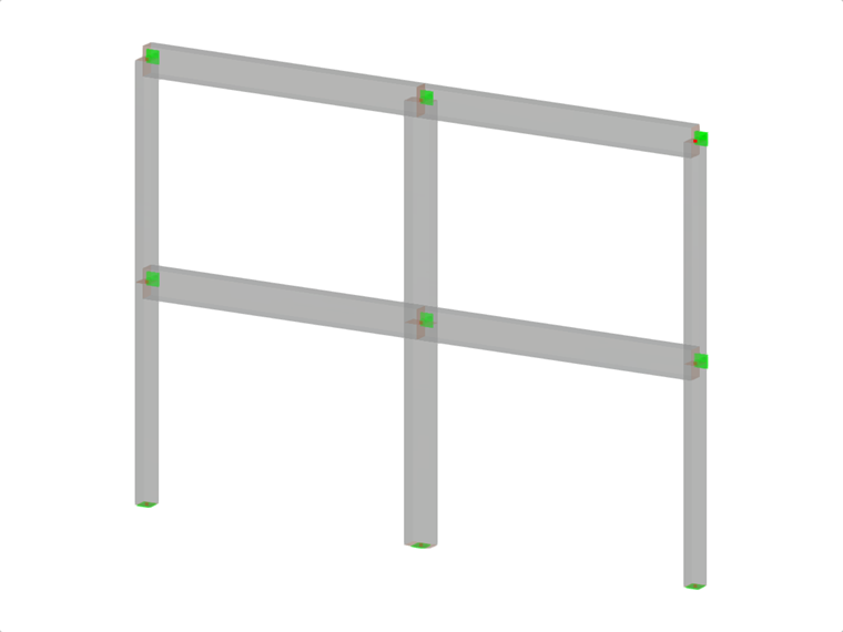
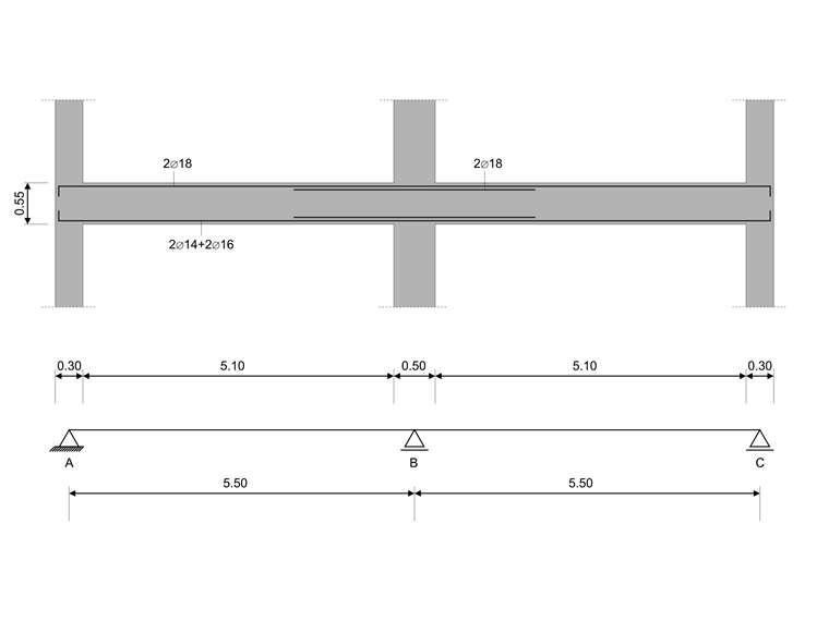
In this verification example, the capacity design values of shear forces on beams are calculated in accordance with EN 1998-1, 5.4.2.2 and 5.5.2.1 as well as the capacity design values of columns in flexure in accordance with 5.2.3.3(2). The system consists of a two span reinforced concrete beam with a span length of 5.50m. The beam is part of a frame system. The results obtained are compared with those in [1].
| Material | Concrete C20/25 | Modulus of Elasticity | E | 30000 | N/mm2 |
| Design value of concrete compressive strength | fcd | 11.333 | N/mm2 | ||
| Reinforcing Steel B400S(C) | Modulus of Elasticity | Es | 200000.000 | N/mm2 | |
| Design yield strength | fyd | 347.826 | N/mm2 | ||
| Geometry | Structure | Beams length | lb | 5.500 | m |
| Columns length | lc | 4.000 | m | ||
| Beams cross-section | Height | h | 550 | mm | |
| Width | b | 300 | mm | ||
| Concrete cover | cnom | 20 | mm | ||
| Columns cross-section | Height | h | 500 | mm | |
| Width | b | 300 | mm | ||
| Concrete cover | cnom | 22 | mm | ||
| Loads | Permanant loads | Dead Load | LC1 | 10.875 | kN/m |
| Dead Load | LC1 | 571.900 | kN | ||
| Dead Load | LC1 | 158.650 | kN | ||
| Imposed loads | Live Load | LC2 | 20.000 | kN/m | |
| Dynamic loads | Modal | LC3 | |||
| Response Spectrum | LC4 |

RFEM Settings
- the ductility class of the model is set to high ductility (DCH)
Results
- Capacity Rule for Shear - Capacity design values of shear forces on beams acc. to EN 1998-1, 5.4.2.2 and EN 1998-1, 5.5.2.1
The design check capacity rule for shear is carried out for member 11 at the face of the supports A (x=0,0 m) and B (x=5,1 m).
Capacity Rule for Shear- Capacity design values of shear forces on beams acc. to EN 1998-1, 5.4.2.2 and EN 1998-1, 5.5.2.1 Parameter Description Unit RFEM Reference Solution Ratio M+Rd,1,y Positive (sagging) moment resistance at member start [kNm] 119.914 118.700 1.01 M-Rd,1,y Negative (hogging) moment resistance at member start [kNm] -86.529 -85.800 1.01 M+Rd,2,y Positive (sagging) moment resistance at member end [kNm] 120.247 118.700 1.01 M-Rd,2,y Negative (hogging) moment resistance at member end [kNm] -170.848 -168.800 1.01 lcl Clear span of beam [m] 5.100 5.100 1.00 VA,g+ψ2q,max Shear force due to quasi-permanent loads for simply supported beam in the face of the support A [kN] 53.550 53.550 1.00 V-A,Ed,max,z Shear force corresponding to maximum negative end moment in z-direction [kN] -14.878 -14.100 1.06*) V+A,Ed,max,z Shear force corresponding to maximum positive end moment in z-direction [kN] 102.213 101.670 1.01 ζ1,max Ratio of design shear forces V-Ed,max / V+Ed,max [-] -0.146 -0.139 1.05 VB,g+ψ2q,max Shear force due to quasi-permanent loads for simply supported beam in the face of the support B [kN] 53.550 53.550 1.00 V-B,Ed,min,z Shear force corresponding to minimum negative end moment in z-direction [kN] -121.978 -121.200 1.01 V+B,Ed,min,z Shear force corresponding to minimum positive end moment in z-direction [kN] -4.887 -5.430 0,90*) ζ2,min Ratio of design shear forces V+Ed,min / V-Ed,min [-] -0.040 -0.045 0.90

*) The absolut difference between those results is less then 1 kN.
- Capacity Rule for Bending - Capacity design of columns in flexure acc. to EN 1998-1, 5.2.3.3(2)
The design check capacity rule for bending is carried out at the face of the supports at member start of column 5.
Capacity Rule for Bending - Capacity design of columns in flexure acc. to EN 1998-1, 5.2.3.3(2) Parameter Description Unit RFEM Reference Solution Ratio M+Rd,c,1,y,5 Positive moment resistance of column 5 [kNm] -294.602 -281.000 1.05 M+Rd,c,1,y,2 Positive moment resistance of column 2 [kNm] -300.046 -295.000 1.02 ΣM+Rd,c,1,y Sum of moment resistances of columns at node 1 (start node) of column 5 [kNm] -594.648 -576.000 1.03 M-Rd,b,1,y,11 Negative moment resistance of beam member 11 (left side) of node [kNm] -170.848 -168.800 1.01 M-Rd,b,1,y,12 Negative moment resistance of beam member 12 (right side) of node [kNm] -120.866 -118.700 1.02 ΣM-Rd,b,y Sum of moment resistances of beams at node B [kNm] -291.714 -287.500 1.01 η+y Design check ratio of positive capacity moments [-] 0.638 0.649 0.98