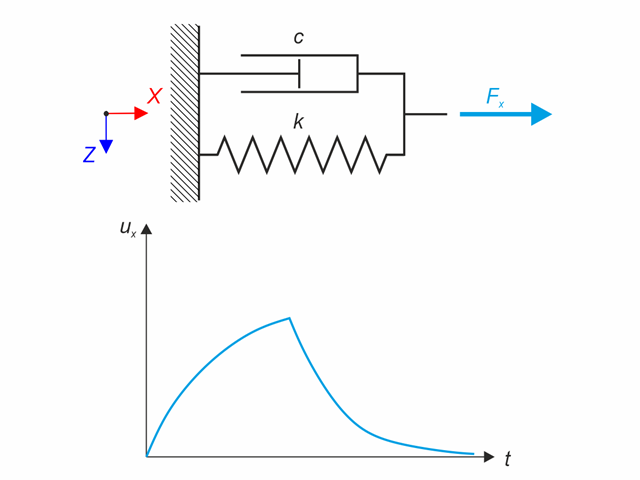
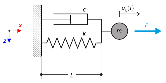
Kelvin-Voigt material model consists of the linear spring and viscous damper connected in parallel. In this verification example there is tested the time behaviour of this model during the loading and relaxation in a time interval 24 hours. The constant force Fx is applied for 12 hours and the rest 12 hours is the material model free of load (relaxation). The deformation after 12 and 20 hours is evaluated. Time History Analysis with Linear Implicit Newmark method is used.
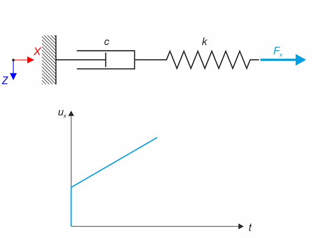
Maxwell material model consists of the linear spring and viscous damper connected in series. In this verification example there is tested the time behaviour of this model. The Maxwell material model is loaded by constant force Fx. This force causes initial deformation thanks to the spring, the deformation is then growing in time due to the damper. The deformation is observed at time of loading (20 s) and at the end of the analysis (120 s). Time History Analysis with Linear Implicit Newmark method is used.

An inner column in the first floor of a three-story building is designed. The column is monolithic connected with the top and bottom beams. The fire design simplified method A for columns according to EC2-1-2 is than proofed and the results compared to [1].
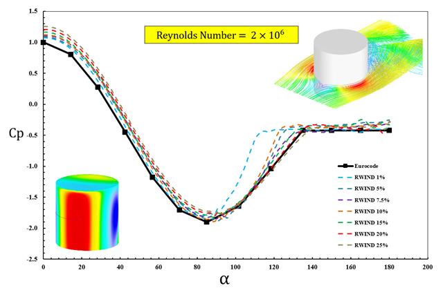
The available standards, such as EN 1991-1-4 [1], ASCE/SEI 7-16, and NBC 2015 presented wind load parameters such as wind pressure coefficient (Cp) for basic shapes. The important point is how to calculate wind load parameters faster and more accurately rather than working on time-consuming as well as sometimes complicated formulas in standards.
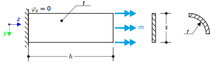
A thin plate is fixed on one side and loaded by means of distributed torque on the other side. First, the plate is modeled as a planar plate. Furthermore, the plate is modeled as one-fourth of the cylinder surface. The width of the planar model is equal to the length of one-fourth of the circumference of the curved model. The curved model thus has almost equal torsional constant to the planar model.
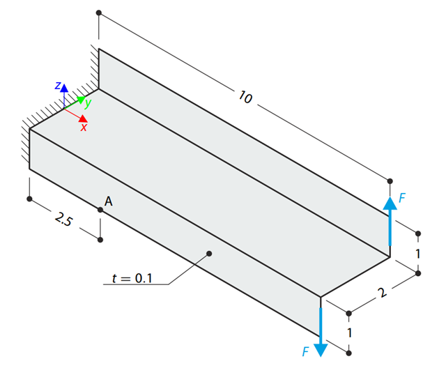
A Z-Section Cantilever is fully fixed at the end and loaded by a torque which, in the case of a shell model, is represented by a couple of shear forces. Determine the axial stress at point A (at mid-surface). The problem is defined according to The Standard NAFEMS Benchmarks.
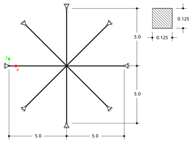
Determine the first sixteen natural frequencies of a double cross with a square cross-section. Each of the eight arms is modeled by means of four beam elements and has a pin support at the end (the x- and y-deflections are restricted). The vibrations are considered only in plane xy. The problem is defined according to The Standard NAFEMS Benchmarks.
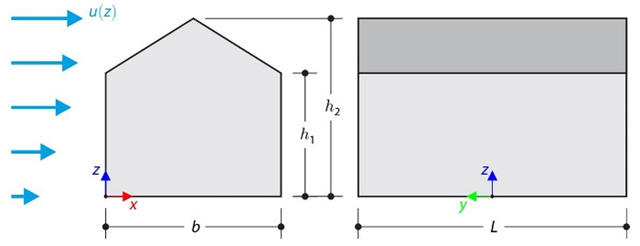
This verification example compares wind load calculations on a duopitch roof building using the ASCE 7-16 standard and using CFD simulation in RWIND Simulation. The building is defined according to the sketch and the inflow velocity profile taken from the ASCE 7-16 standard.

This verification example compares wind load calculations on a flat roof building using the ASCE 7-16 standard and using CFD simulation in RWIND Simulation. The building is defined according to the sketch and the inflow velocity profile taken from the ASCE 7-16 standard.
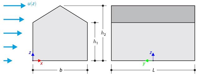
The verification example compares wind load calculation on a building with a duopitch roof using the standard EN 1991-1-4 and using CFD simulation in RWIND Simulation. The building is defined according to the sketch, and the inflow velocity profile is taken according to the standard EN 1991-1-4.
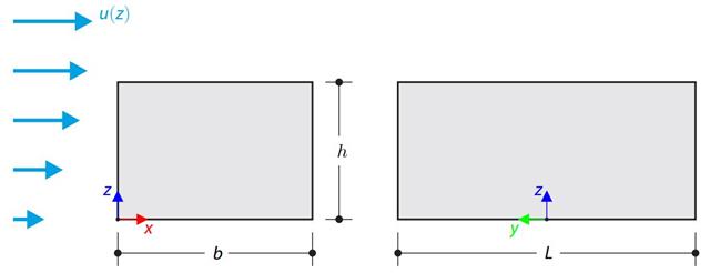
The verification example compares wind load calculation on a building with a flat roof using the standard EN 1991-1-4 and using CFD simulation in RWIND Simulation. The building is defined according to the sketch, and the inflow velocity profile is taken according to the standard EN 1991-1-4.
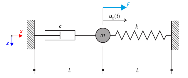
A single-mass system with dashpot is subjected to a constant loading force. Determine the spring force, damping force, and inertial force at the given test time. In this verification example, the Kelvin--Voigt dashpot (namely, a spring and a damper element in serial connection) is decomposed into its purely viscous and purely elastic parts, in order to better evaluate the reaction forces.
A single-mass system with dashpot is subjected to constant loading force. Determine the deflection and velocity of the dashpot endpoint in the given test time.
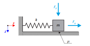
A simple oscillator consists of mass m (considered only in the x-direction) and linear spring of stiffness k. The mass is embedded on a surface with Coulomb friction and is loaded by constant-in-time axial and transverse forces.
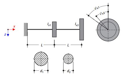
A double‑mass system consists of two shafts and two masses represented by the corresponding moments of inertia, concentrated in a given distance as nodal masses. The left shaft is fixed, and the right mass is free. Neglecting the self‑weight of the shafts, determine the torsional natural frequencies of the system.
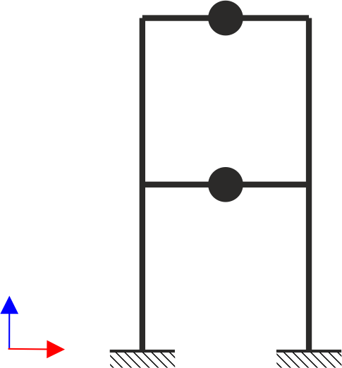
A two‑story, single‑bay frame structure is subjected to earthquake loading. The modulus of elasticity and cross‑section of the frame beams are much larger than those of the columns, so the beams can be considered rigid. The elastic response spectrum is given by the standard SIA 261/1:2003. Neglecting self-weight and assuming the lumped masses are at the floor levels, determine the natural frequencies of the structure. For each frequency obtained, specify the standardized displacements of the floors as well as equivalent forces generated using the elastic response spectrum according to the standard SIA 261/1.2003.
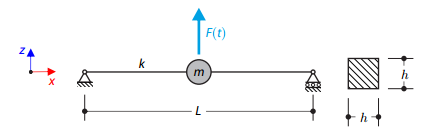
A long, thin beam is carrying a concentrated mass and is loaded by a time-dependent force. It is simply supported. The problem is described using the following parameters. Determine the deflections in the given test times.
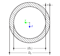
Determine the torsional constant for the cross-section of the tube (annular area) analytically, and compare the results with the numerical solution in RFEM 5 and RSTAB 8 for various wall thicknesses.