


Do you have any questions about Dlubal products or need assistance in selecting the right one for your project?
I'm here to help. You can easily reach me through the contact options provided below.
Looking forward to hearing from you!


Automatic Generation of Load Combinations
Standards
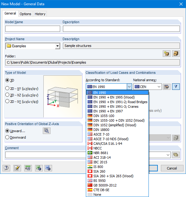
The Base Data dialog box includes a wide range of standards and the option to create combinations automatically. The following standards are available:
-
 EN 1990:2002
-
EN 1990 + EN 1995:2004 (Timber)
-
EN 1990 + EN 1991-2; Road bridges
-
EN 1990 + EN 1991-3; Cranes
-
EN 1990 + EN 1997
-
 to DIN 1055-100:2001-03
-
DIN 1055-100 + DIN 1052:2004-08 (timber)
-
DIN 1055-100 + DIN 18008 (Glass)
-
DIN 1052 (simplified) (timber)
-
DIN 18800:1990
-
 ASCE 7‑10
-
ASCE 7-10 NDS (Wood)
-
ACI 318-14
-
IBC 2015
-
 CAN/CSA S 16.1-94:1994
-
NBCC: 2005
-
 NBR 8681
-
 IS 800:2007
-
 SIA 260:2003
-
SIA 260 + SIA 265:2003 (timber)
-
 BS 5950-1:2000
-
 GB 50009-2012
-
 CTE DB-SE
For the European standards (EC), the following National Annexes are available:
-
DIN EN 1990/NA:2009-05 (Germany)
-
 NBN EN 1990 - ANB: 2005 (Belgium)
-
 BDS EN 1990:2003/NA:2008 (Bulgaria)
-
 DK EN 1990/NA:2007-07 (Denmark)
-
 SFS EN 1990/NA:2005 (Finland)
-
 NF EN 1990/NA:2005/12 (France)
-
 ELOT EN 1990:2009 (Greece)
-
 UNI EN 1990/NA:2007-07 (Italy)
-
 IS EN 1990:2002 + NA:2010 (Ireland)
-
 LVS EN 1990:2003/NA:2010 (Latvia)
-
 LST EN 1990/NA:2010-11 (Lithuania)
-
 LU EN 1990/NA:2011-09 (Luxembourg)
-
 MS EN 1990:2010 (Malaysia)
-
 NEN EN 1990/NA:2006 (Netherlands)
- NS EN 1990/NA:2008 (Norway)
-
 ÖNORM EN 1990:2007-02 (Austria)
-
 NP EN 1990:2009 (Portugal)
-
 PN EN 1990/NA:2004 (Poland)
-
 SR EN 1990/NA:2006-10 (Romania)
-
 SIST EN 1990: 2004/A1:2005 (Slovenia)
-
 SS EN 1990:2008 (Singapore)
-
 SS EN 1990/BFS 2010:28 (Sweden)
-
 STN EN 1990/NA:2009-08 (Slovakia)
-
UNE EN 1990 2003 (Spain)
-
 CSN EN 1990/NA:2004-03 (Czech Republic)
-
BS EN 1990/NA:2004-12 (the United Kingdom)
-
 TKP EN 1990/NA:2011 (Belarus)
-
 CYS EN 1990:2002 (Cyprus)
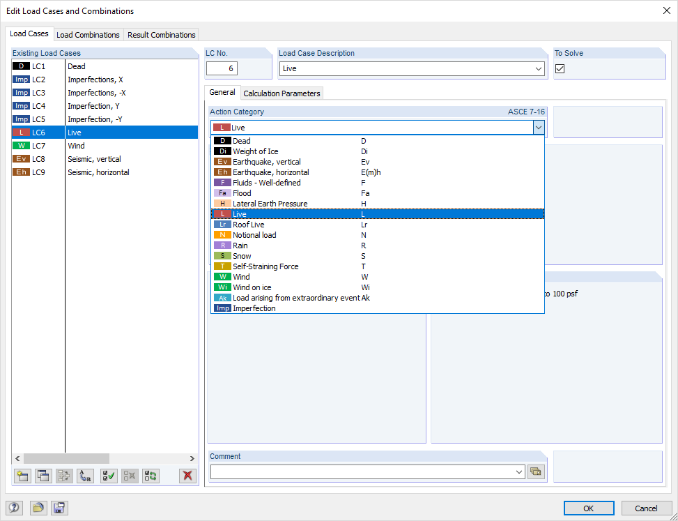
Load Cases / Action Types
In the "Edit Load Cases and Combinations" dialog box, you can create and edit load cases as well as generate action, load, and result combinations. It is possible to assign various action types to the individual load cases in accordance with the selected standard. If several loads have been assigned to one action type, they can act simultaneously or alternatively (for example, wind from the left or right).
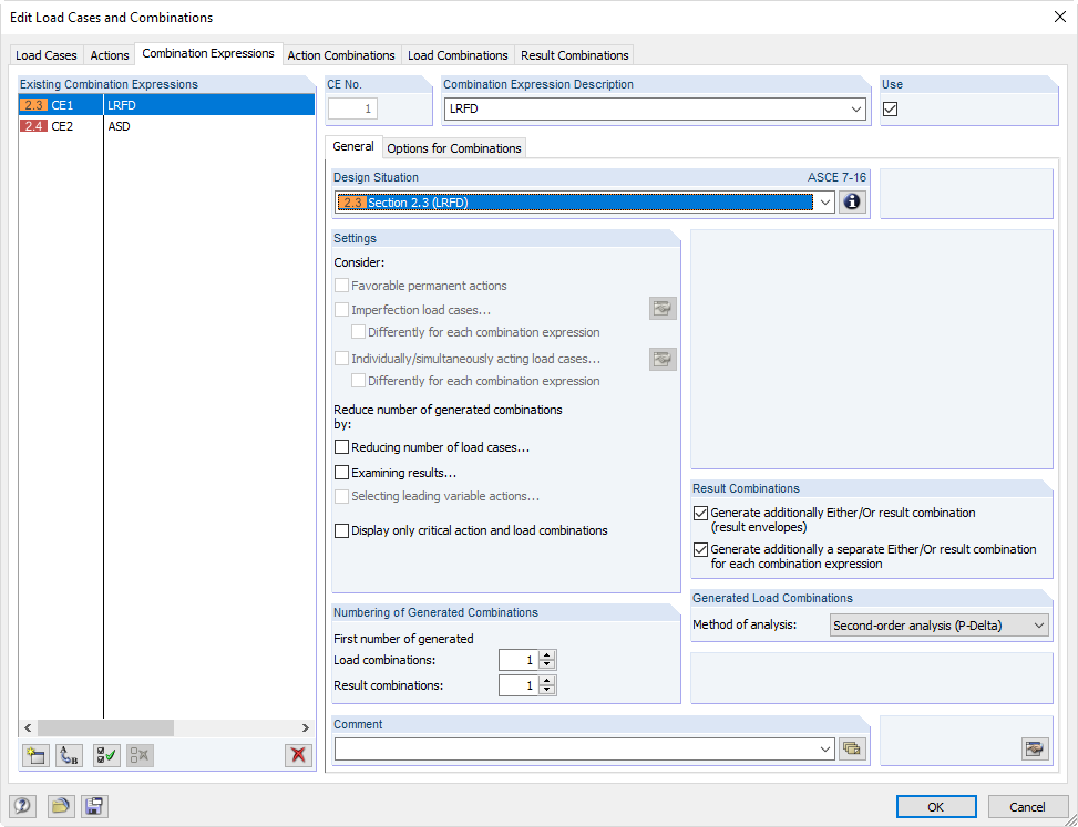
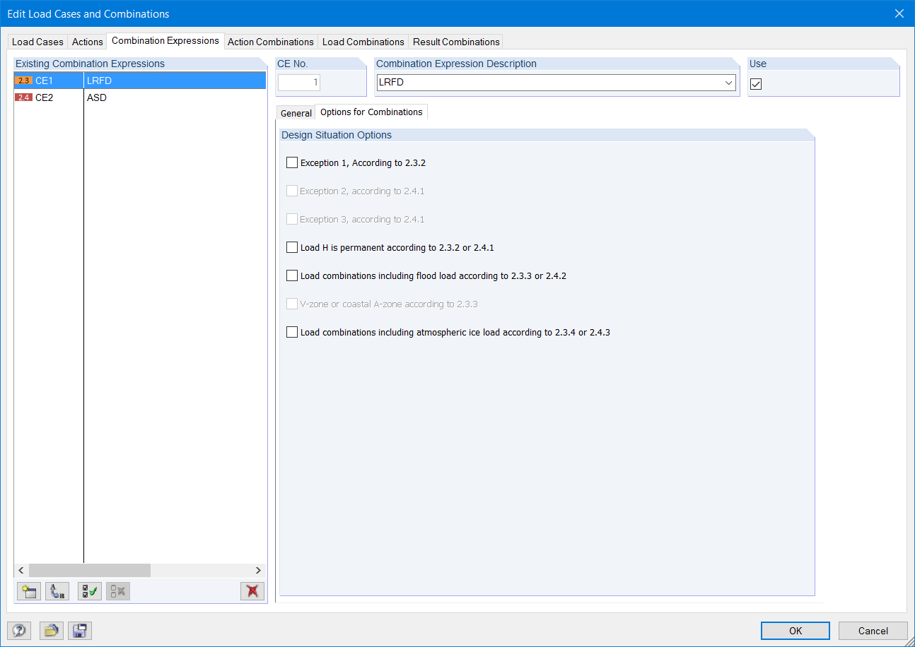
Combination expression
For the combination of actions in the ultimate and the serviceability limit state, you can select various design situations according to the standard (for example, ULS (STR/GEO) - permanent/transient, SLS - quasi-permanent, and others).
Furthermore, there is the option to integrate imperfections in the combination and to determine load cases that should not be combined with other load cases (for example, construction load for roof not combined with snow load).
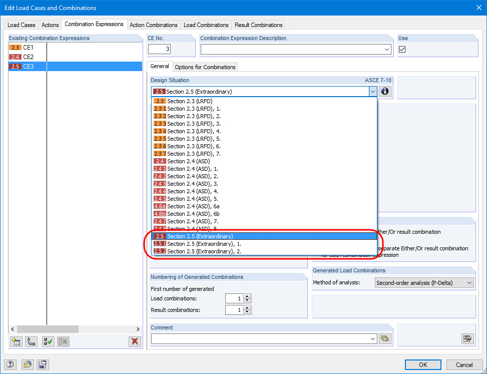
Accidental Design Situation (such as North German Plain)
When you select the design situation 'Accidental', accidental actions such as earthquake, explosion loads, collisions, and others are automatically taken into account. When applying German standards, you can automatically consider the 'North German Plain' by selecting the design situation 'Accidental - Snow'.
Reduction of Automatically Generated Combinations
There are three options to reduce the number of combinations. The first two procedures are only available for the generation of load combinations, not for result combinations.
The first option allows for automatic analysis of all load case results (internal forces, deformations, and so on) of selected elements. Then, the program will generate only those combinations that include the load cases producing a maximum or minimum. In addition, you can define a maximum number of relevant load cases, or neglect load cases with a very small contribution to the maximum and minimum values.
The second option allows for automatic evaluation of generated temporary or user-defined result combinations. Then, only the governing load combinations are created.
The third option to reduce the number of generated combinations is to classify only selected actions as leading actions.
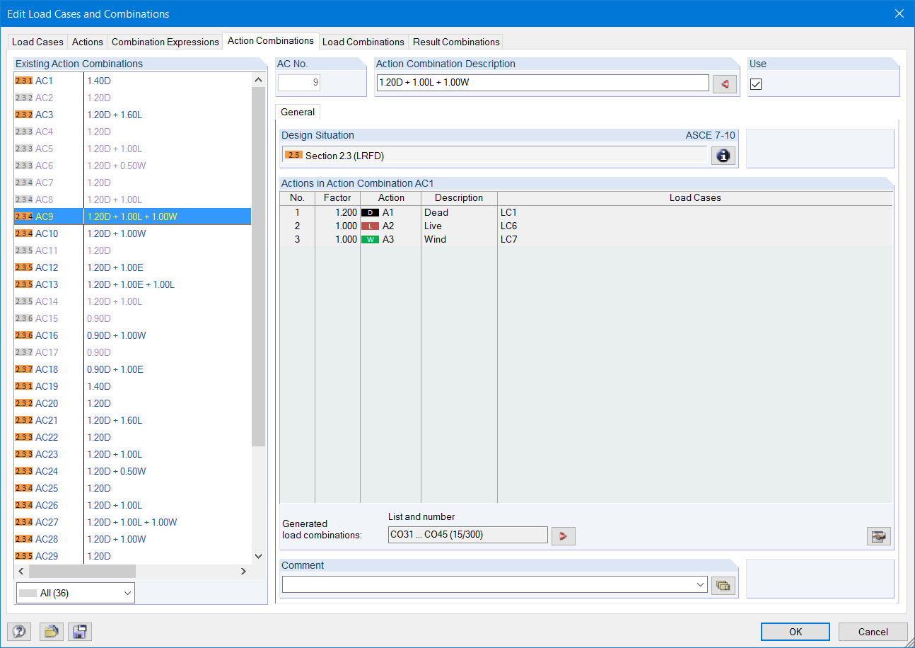
Action Combinations
The actions are automatically superimposed in accordance with combination expressions and then displayed as "action combinations". It is possible to define which action combinations will eventually be used for the generation of load or result combinations. The generated action combinations can be used to estimate how the combination expressions affect the number of combinations.
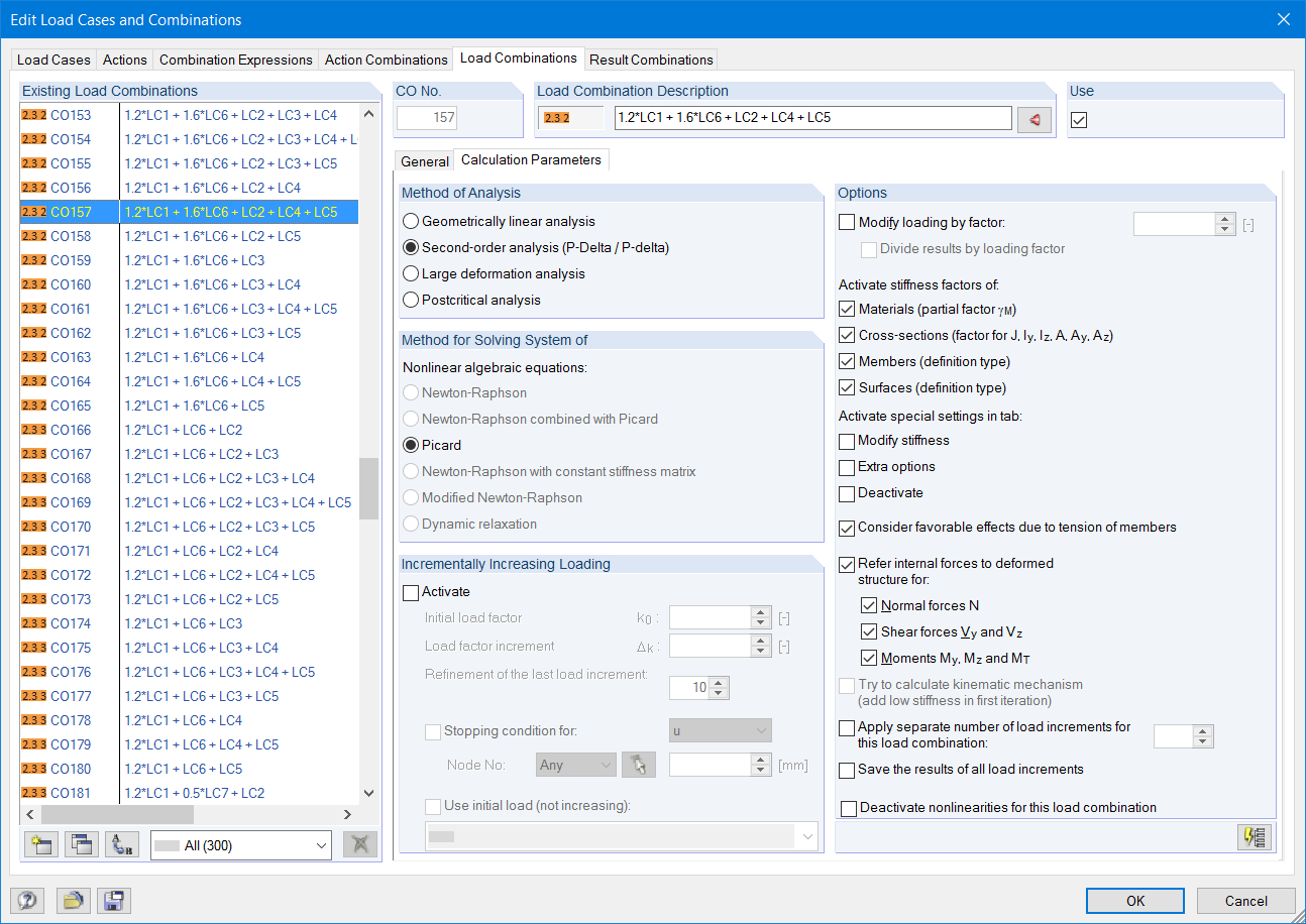
Load combinations
The load cases included in load combinations are added together and then calculated in consideration of the corresponding factors (partial safety and combination factors, coefficients regarding consequence classes, and so on). The load combinations can be created automatically in compliance with the combination expressions of the standard. The calculation can be performed according to the geometrically linear, second-order, or large deformation or as per the post-critical analysis. Optionally, you can define whether the internal forces should be related to the deformed or non-deformed structure.
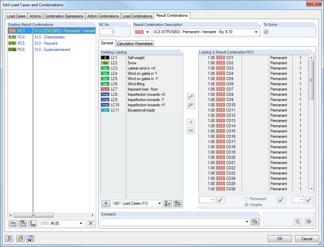
Result Combinations
The load cases included in the result combinations are calculated first. Then, the results are superimposed by taking into account the corresponding factors. In the result combinations, you can superimpose the results of load cases, load combinations, and other result combinations. Internal forces are added together by default. However, there is the option of a square addition, which is relevant for dynamic analysis.
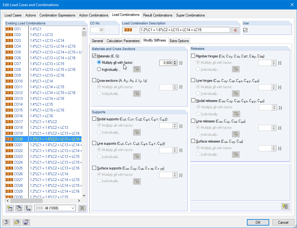
Modifying Stiffnesses / Considering Initial Deformations
In the individual load cases or combinations, there is the option to modify the stiffnesses of materials; cross-sections; nodal, line and surface supports; and member and line hinges for all or selected members. Furthermore, it is possible to consider initial deformations from other load cases or load combinations.