550 Results
View Results:
Sort by:
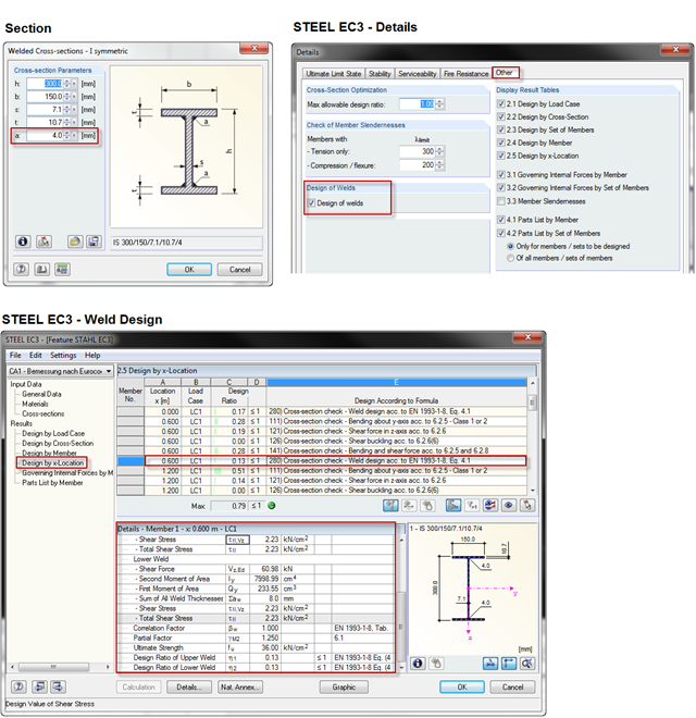
When using a welded profile, weld seam verification can also be carried out in RF-/STEEL EC3 as part of the design. The program performs the typical designs according to EN 1993‑1‑8.
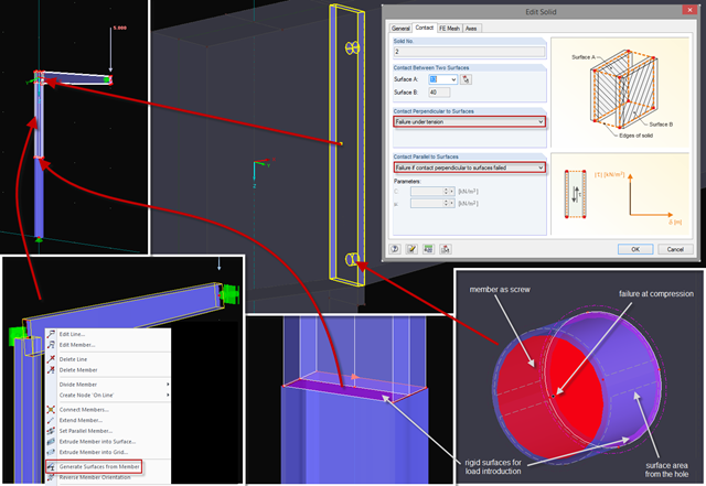
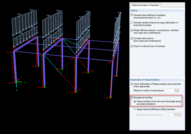
Sometimes, a detailed examination is needed of problematic areas of a joint or the stiffness of a frame joint. The following tips can help you with this. As an example, a frame joint was modeled using RF‑FRAME‑JOINT Pro and members, and used as a basis.
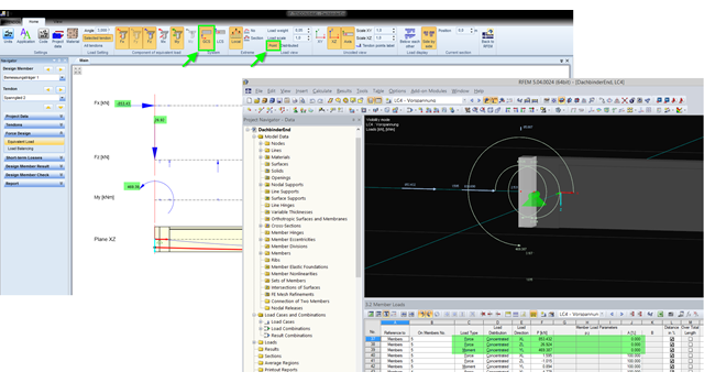
The equivalent loads determined in RF-TENDON due to prestress are transferred in RFEM as member loads or as line loads. A member load is used for member types with their own stiffness; a line load is used for member types without their own stiffness. In order to understand which values of the concentrated loads are to be transferred from RF‑TENDON to RFEM, you should use the following display settings: ~ Reference of the loads to the global coordinate system (GCS), ~ Load display: "Point"

Diagonals of double angles are used for pipe bridge construction and for truss girders, among other things. They are usually subjected to tension, but it is necessary to transfer them in smaller compression forces with regard to the load application. In the case of slender diagonals in particular, you should also consider the bending due to self‑weight.
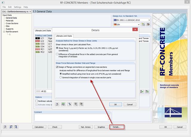
With the latest version of CONCRETE and RF-CONCRETE Members, it is possible to perform shear design for the connection of compression and tension flanges on a T-beam web.

A previous article describes the design of double angles. It deals with analysis performed on a single member.
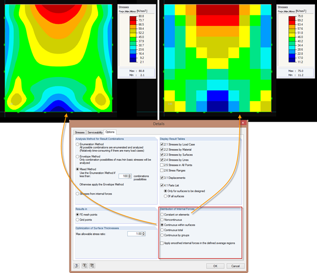
Just as in the RFEM Display Navigator, you can set the distribution of internal forces in surfaces in RF‑STEEL Surfaces. Since deformations are always the result of the FEM calculation, the corresponding forces will be recalculated. This means that the internal forces on an FEM element are calculated depending on the composition (triangular or square) in three or four places. In order to obtain continuous internal forces and thus a smoothed distribution, these internal forces have to be interpolated. Interpolation is done by selecting the "Distribution of internal forces" option in the surfaces.
In RFEM and RSTAB, the internal forces of individual load combinations are determined according to the second-order analysis by default. If you use the RF‑CONCRETE add‑on module for stability analysis of reinforced concrete columns, you can change the calculation method of LCs to the linear static analysis, since the effects of the second‑order analysis are already considered in the calculation according to the model column method in RF‑CONCRETE Columns (nominal curvature method).
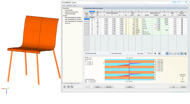
In RF‑LAMINATE, you can also design curved quadrangle surfaces. In the example in the figure, the cross-laminated timber layers of a chair are designed.
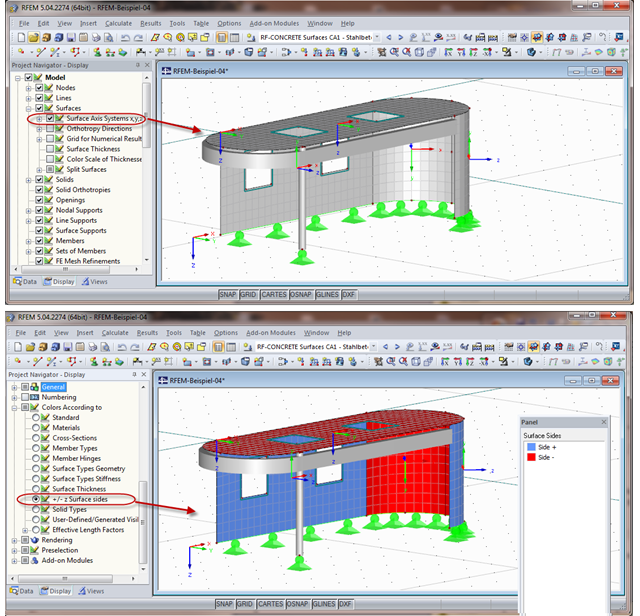
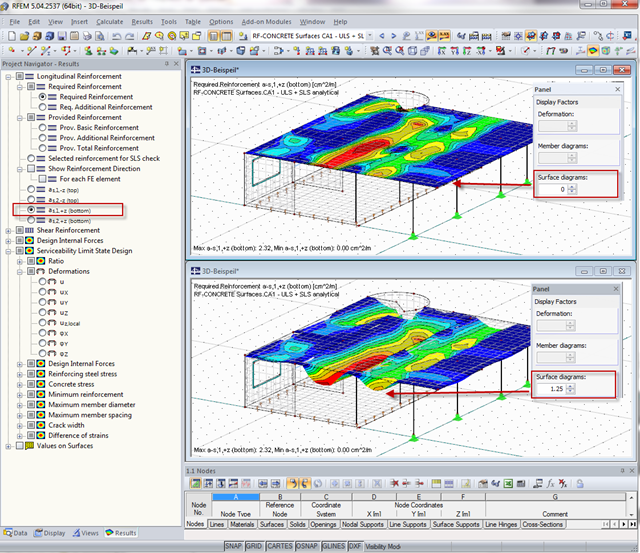
When calculating the surface reinforcement in RF-CONCRETE Surfaces, the result values for both surface sides +/- z are available. If you are unsure which side of a surface is the positive or the negative z side, you can hide the local coordinate system of each surface in the RFEM Project Navigator - Display under "Model" → "Surfaces" → "Surface Axis Systems x,y,z". In the case of complex structures, this can quickly become confusing. Displaying multiple axis systems makes it difficult to recognize the incorrect direction of a surface, for example (see the figure on the top).
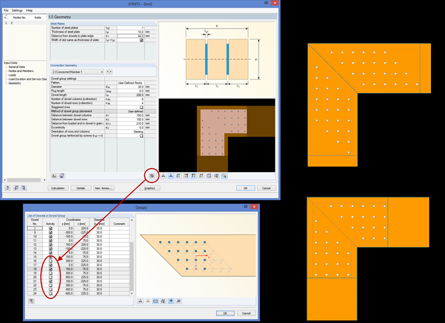
In RF‑/JOINTS Timber, you can remove an individual dowel from the calculation, thus creating any dowel layout. The calculation disregards these removed dowels for the ultimate limit state design, as well as for the net timber cross‑section analysis and the rotational spring stiffness determination.
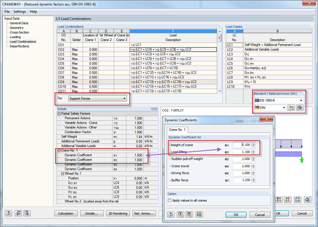
NCI to DIN EN 1993‑6, Part 2.3.1 allows reductions of dynamic coefficients for values ≧ 1.1. Therefore, you can use these reduced support loads for designing support and hanger structures. In CRANEWAY, if you select National Annex "DIN" and dynamic coefficients ≧ 1.1, the reduction is considered automatically.

In order to design longitudinal reinforcement for the serviceability limit state, it is necessary to enable this function. This is possible in Window 1.1 General Data under the "Serviceability Limit State" tab. After you select the "Analytical..." method of checking, you can select the corresponding additional options in the section for determining the longitudinal reinforcement of the "Settings of Analytical Method of Serviceability Limit State Design" window.
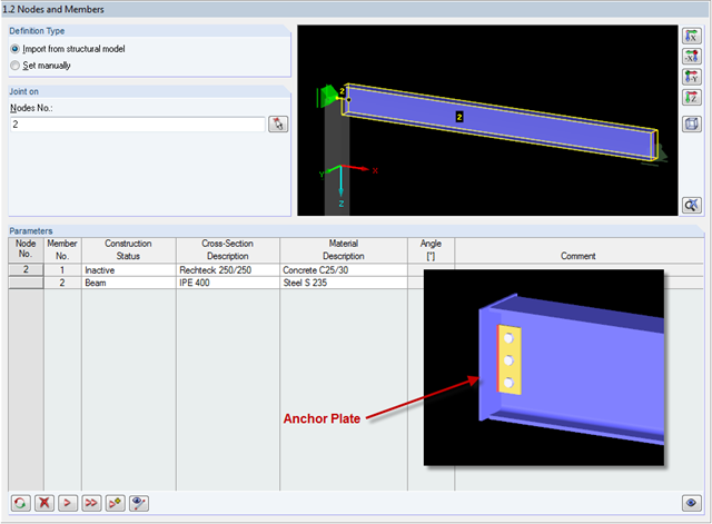
In RF-/JOINTS Steel - Pinned, it is possible to design connections without a supporting structure (for example, columns). In this case, the beam is connected to an anchor plate. How is this kind of connection defined?
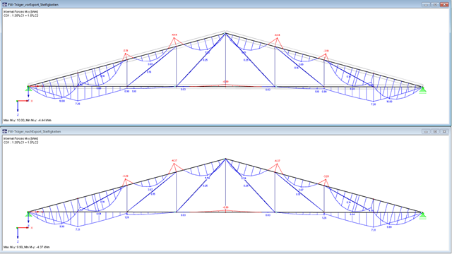
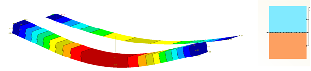
In RF-/JOINTS Timber - Steel to Timber, you can consider the eccentricities of a connection during the calculation. The figure shows different internal forces without consideration of the eccentricity (above) and withn consideration of the eccentricity (below).

In RF-CONCRETE Surfaces, you can use the "Filter Points" function when evaluating results by points. This filter function allows for a user-defined group of points that can be defined in the result window. You can select the filter in Window 2.3 Required Reinforcement by Points, among others.
When calculating the surface reinforcement in RF-CONCRETE Surfaces, the result values for both surface sides +/- z are available. A previous post describes how to display the local surface sides in RFEM.
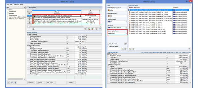
As of version X.04.0096, RF‑/TIMBER Pro also allows you to design other material categories such as softwood, hardwood, and glulam timber as a member in compliance with EN 1995‑1‑1. The design spectrum has been expanded for the material categories LVL, Plywood, OSB, Particleboard, and Fiberboard. In order to facilitate the selection in the materials library, there is another function for targeted filtering by plate or wall stress.
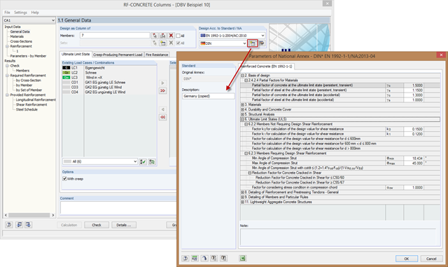
In order to meet the requirements for the parameters of special buildings modified according to standard adjustments, you can create new National Annexes from an existing one. To do this, copy the National Annex and adjust the parameters to the requirements.
For recurring elements such as certain structural components or standard parts, you can use the parametrization of a basic model. In the program, the main elements do not represent components but the corresponding node and therefore, they have to be parameterized. For example, a member is not defined by the length, but by the start and end nodes. In this way of modeling, complex formulas may occur especially in the case of three-dimensional structures.
Shoring braces usually obtain the "tension member" type. There are a few specifics to note because in the case of uniform, symmetrical structures and solely vertical loads, an error message often appears as follows: "The model is unstable in node No. 20. Free movement around Y-direction."
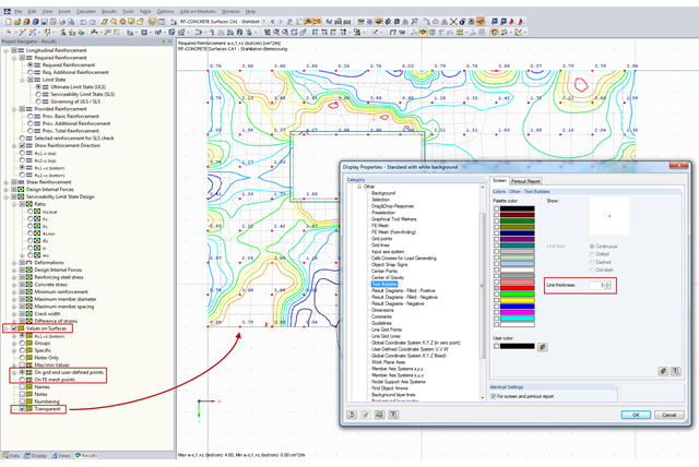
You can document the results of RF‑CONCRETE Surfaces graphically in the printout report. To do this, the "Values on Surfaces" setting is often selected in the Results Navigator of RF‑CONCRETE Surfaces. A text bubble including a result value is displayed, and depending on the settings in the Results Navigator, it can be displayed on the surface grid points, manually defined points, or in FE mesh points.
RF-LAMINATE allows free definition of materials. Thus, you can combine any compositions of different materials. The combination of concrete and timber is possible as well. However, the rigid composite must be provided when defining such a composition. In RF-LAMINATE, you can consider full shear coupling or no shear coupling at all.
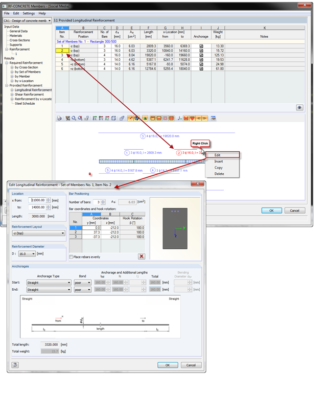
With the introduction of OSG graphics for the representation of design reinforcement in RF‑CONCRETE Members and CONCRETE, you can also select the reinforcement position directly in the graphic. Right-click the mouse to open the context menu where you can edit, copy, or delete the selected reinforcement position.
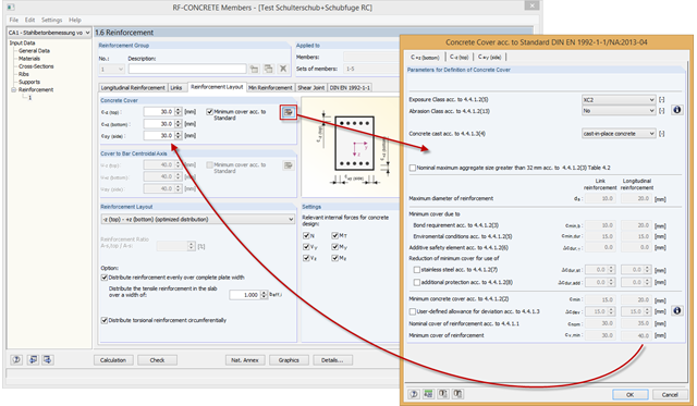
RF-/CONCRETE automatically determines the minimum concrete cover according to the standard. The calculation is based on the exposure class, the abrasion class, and the concrete cast.
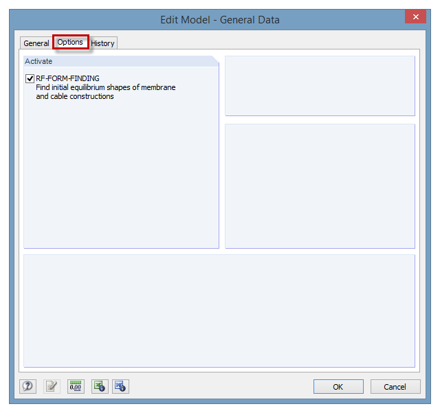
The RF‑FORM‑FINDING add‑on module can be activated in the "Edit Model - General Data" window, "Options" tab. By activating the module, a new RF‑FORM‑FINDING load case is created and an additional menu appears in the main program, allowing for the definition of prestress conditions for membrane and cable elements.
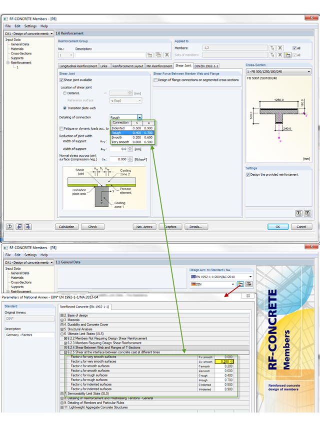
The shear resistance design value of a joint depends mainly on the formation or the roughness of the connection. When determining the ultimate limit state, this is considered by the factors µ (friction) and c (adhesion percentage of the contact area of the composite concrete).
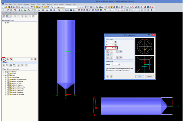
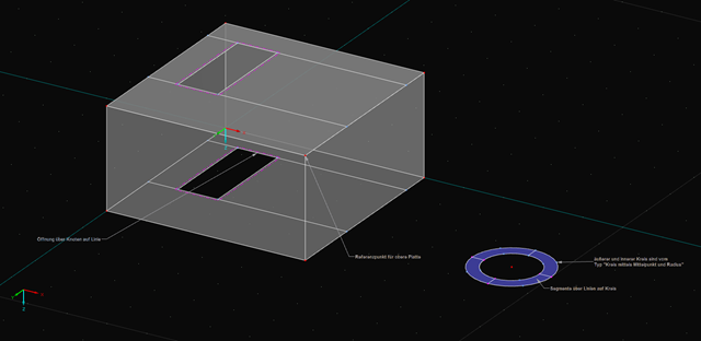
If you consider rotating the structure shown in the figure around the global Y‑axis, this might be not straightforward. In order to achieve better handling, the axis is always locked in the direction of your view. In the case of very high structures, it may be helpful to rotate the view about 90 degrees in the viewing direction.
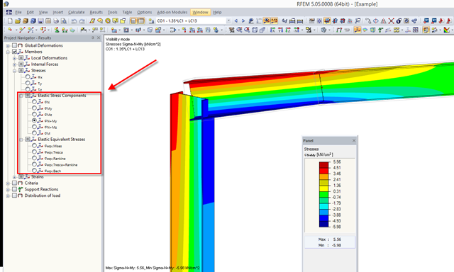
RFEM 5.04.xx allows for graphical visualization of normal and shear stress of members (this feature is available only if the RF‑STEEL add‑on module is licensed).
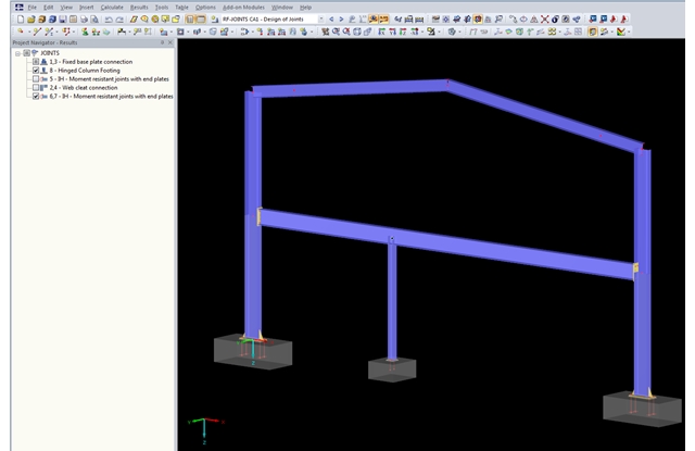
The updated Results Navigator of RF‑JOINTS allows you to display the results of different module cases simultaneously. Thus, you can display all column base designs at the same time in order to perform collision checks of the foundations, for example.