33 Results
View results:
Sort by:

Silos are used as large containers for storage of bulk materials such as agricultural products or source materials as well as intermediates of industrial production. The structural engineering of such structures requires a precise knowledge of the stresses due to particulate solids in the building structure. The standard EN 1991‑4 "Actions on Silos and Tanks" [1] provides the general principles and requirements for determining these actions.
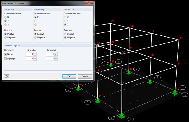
When modeling a structure, irregular numbering of objects may occur due to copying, dividing lines and members, and so on. Automatic renumbering allows you to restructure the numbering and thus to improve the clear arrangement. This function is applicable to nodes and members as well as for lines, surfaces, and solids in RFEM.
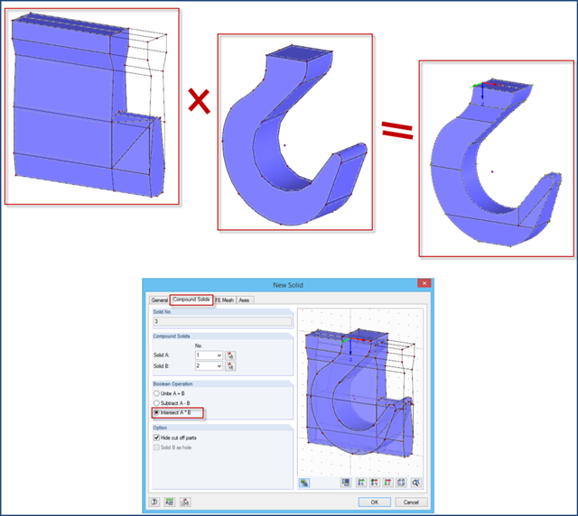
The "Intersect" option may facilitate the modeling of complex solids. This option is available in the shortcut menu after selecting two solids.
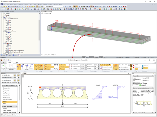
Prestressed concrete slabs consist of composite, uniaxially stressed hollow plates with a width of about 1.20 m. These elements are prestressed with pre-tension in a precast concrete plant. The precasting is usually done with slipformers. Due to the lesser self‑weight of the non‑solid slab and the existing prestress, these precast prestressed hollow core slabs show a lower deflection than loosely reinforced slabs made of solid concrete.

For designing glass in the RF‑GLASS add‑on module, you can use one of two calculation methods: a 2D or a 3D calculation. The main difference between these design options is the automatic modeling of the layers in a temporary model. In a 2D calculation, each layer is generated as a surface element (plate theory); in a 3D calculation, it is generated as a solid. Depending on the selected layer composition, you can either select an option or find it preselected by the program.
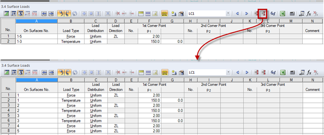
The load tables provide a simple option to control the applied loads. Dividing loads into individual lines is expedient. After dividing loads into the load table, the load data are displayed by a structural element (nodes, members, lines, surfaces, or solids). Thus, the load data analysis of each structural element is facilitated. The load case data can be compressed later.
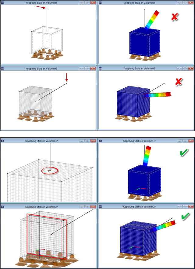
If a slender component (member) is to be connected to a massive component (solid), it is necessary to pay attention to the correct connection of both elements.
Contact solids can be created between two flat surfaces or between two cylindrical shells. However, if the area of the contact problem is a little more complicated, it is necessary either to simplify the system so that the requirements of a contact solid can be met, or go back to the "old" modeling style using a rod model.

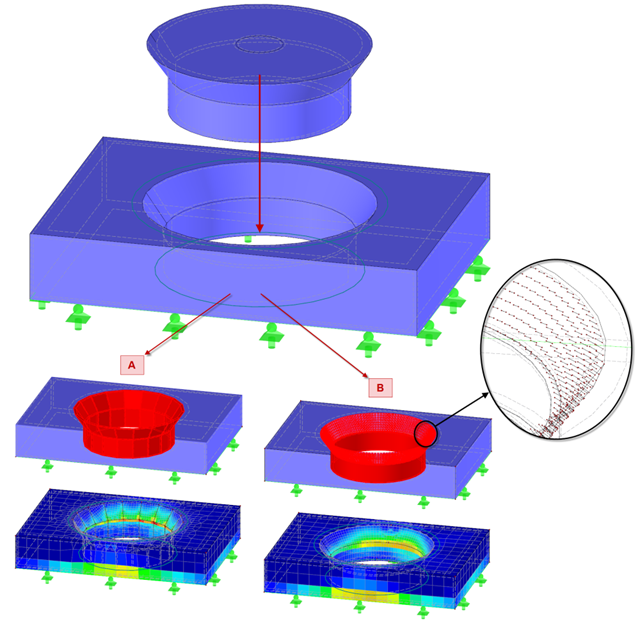
In RFEM, you can display the contact properties between two surfaces by means of contact solids. Among other things, you should ensure that both contact surfaces of a contact solid have the same integrated objects. Therefore, when modeling the contact surfaces, we recommend using the copy function in order to create the second contact surface.

In RFEM, you can display the contact properties between two surfaces by means of contact solids.