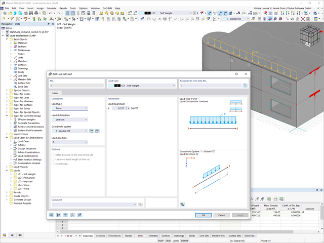
Now, you have new options for your design: With the introduction of line sets, surface sets, and solid sets, new load options have also been added for loading these sets. Try them yourself!
- Design of the following geometrical types:
- Single-span beams with and without cantilevers
- Continuous beams with and without cantilevers
- Hinged girder system (Gerber beams) with and without cantilevers
- Automatic generation of wind and snow loads
- Automatic creation of required combinations for the ultimate and serviceability limit states, as well as fire resistance design
- For design according to EC 5 (EN 1995), the following National Annexes are available:
-
 DIN EN 1995-1-1/NA:2013-08 (Germany)
 -
 NBN EN 1995-1-1/ANB:2012-07 (Belgium)
 -
 DK EN 1995-1-1/NA:2011-12 (Denmark)
 -
 SFS EN 1995-1-1/NA:2007-11 (Finland)
 -
 NF EN 1995-1-1/NA:2010-05 (France)
 -
 UNI EN 1995-1-1/NA:2010-09 (Italy)
 -
 NEN EN 1995-1-1/NB:2007-11 (Netherlands)
 -
 ÖNORM B 1995-1-1:2015-06 (Austria)
 -
 PN EN 1995-1-1/NA:2010-09 (Poland)
 -
 SS EN 1995-1-1 (Sweden)
 -
 STN EN 1995-1-1/NA:2008-12 (Slovakia)
 -
 SIST EN 1995-1-1/A101:2006-03 (Slovenia)
 -
 CSN EN 1995-1-1:2007-09 (Czech Republic)
 -
 BS EN 1995-1-1/NA:2009-10 (the United Kingdom)
-
- Consideration of optimization options by user specifications according to the respective standard:
- Shear force reduction of single loads near support
- Shear force reduction of load introduction at the cross-section top point
- Moment redistribution in support zone
- Reduction of torsional stress by means of user-defined entry of moment
- Increase of bending stiffnesses for flat-ended or edgewise bending strains
- Simple geometry input with illustrative graphics
- Extensive material library for both standards
- Optional extension of material library by further materials
- Extensive library of permanent loads
- Allocation of framework to service classes and specification of service class categories
- Determination of design ratios, support forces, and deformations
- Info icon indicating successful or failed design
- Color reference scales in result tables
- Direct data export to MS Excel
- Program languages: English, German, Czech, Italian, Spanish, French, Portuguese, Polish, Chinese, Dutch, and Russian
- Verifiable printout report, including all required designs. Printout report available in many output languages; for example, English, German, French, Italian, Spanish, Russian, Czech, Polish, Portuguese, Chinese, and Dutch.
- Direct import of stp files from various CAD programs
.png?mw=640&hash=eaf8e422e9b3dcfb04a920c1d3bf09c1bef0d59a)
General
- Beam to Column joint category: connection possible on the column flange as well as on the column web
- Beam to Beam joint category: optional arrangement of ribs on the opposite side
- Bolt sizes from M12 to M36 with the strength grades 4.6, 5.6, 8.8, and 10.9
- Arbitrary bolt hole spacing and edge distances
- Notching of the beam is possible
- Connection with pure shear loading, pure normal force load (tension joint), or possible combination of normal and shear forces
- Checking compliance with the requirements for pinned joints
- Check of the minimum and maximum bolt hole spacing and edge distances
Web cleat connections
- One or two vertical and up to 10 horizontal bolt rows possible at each leg
- Wide range of equal and unequal angles
- Possible to modify angle orientation
- Designs:
- Shear, bearing resistance, and tension design of bolts
- Shear, bending, and tension design of angles considering deduction of bolt hole
- Shear and tension design of girder web considering deduction of bolt hole
- Tension transmission into the column with the T-stub model
- Notching at the critical section
Fin plate connection
- One or two vertical and up to 10 horizontal bolt rows are possible
- Flexible size of the fin plate
- Location of the fin plate can be modified
- Designs:
- Shear and bearing resistance design of bolts
- Shear, bending, and tension design of fin plates considering deduction of bolt hole
- Stability analysis of long, slender fin plates
- Shear and tension design of girder web considering deduction of bolt hole
- Weld as fillet weld
- Notching at the critical section
End plate connection
- Two or four vertical and up to 10 horizontal bolt rows
- Flexible size of the end plate
- Location of the fin plate can be modified
- Designs:
- Shear, bearing resistance, and tension design of bolts
- Shear and bending design of end plates considering deduction of bolt hole
- Shear and tension design of girder web
- Tension transmission into the column with the T-stub model
- Weld as fillet weld
- Notching at the critical section
End plate connection with cleat
- Fixation of the beam by end plate with two bolts
- Flexible size of cleat and end plate
- Designs:
- Load introduction into the beam according to EN 1993-1-5, Chapter 6
- Support of the stabilizing moment by the bolts and welds at the end plate
- Cleat
- Cleat welds as fillet welds
- Tension transmission into the column with the T-stub model
- Craneway and weld stress analysis
- Craneways and weld fatigue design
- Deformation,
- Plate buckling analysis for wheel load introduction
- Stability analysis for lateral torsional buckling according to the second-order analysis of torsional buckling (1D FEA element)
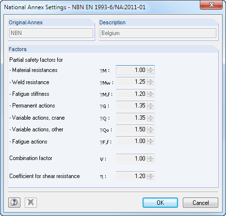
For the design according to Eurocode 3, the following National Annexes are available:
-
DIN EN 1993-6/NA:2010-12 (Germany)
-
NBN EN 1993-6/ANB:2011-03 (Belgium)
-
SFS EN 1993-6/NA:2010-03 (Finland)
-
NF EN 1993-6/NA:2011-12 (France)
-
UNI EN 1993-6/NA:2011-02 (Italy)
-
 LST EN 1993-6/NA:2010-12 (Lithuania)
 -
NEN EN 1993-6/NB:2012-05 (Netherlands)
-
 NS EN 1993-6/NA:2010-01 (Norway)
 -
SS EN 1993-6/NA:2011-04 (Sweden)
-
CSN EN 1993-6/NA:2010-03 (Czech Republic)
-
BS EN 1993-6/NA:2009-11 (United Kingdom)
-
 CYS EN 1993-6/NA:2009-03 (Cyprus)
In addition to the National Annexes listed above, you can also define a specific NA, applying user-defined limit values and parameters.
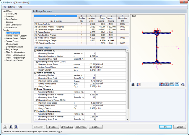
All results are arranged in result windows sorted by different topics. The design values are illustrated in the corresponding cross-section graphic. The design details cover all intermediate values.
General Stress Analysis
CRANEWAY performs the general stress analysis of a craneway girder by calculating the existing stresses and comparing them with the limit normal, limit shear, and limit equivalent stresses. Welds are also subjected to the general stress analysis with regard to parallel and vertical shear stresses and their superposition.
Fatigue Design
Fatigue design is performed for up to three cranes operating at the same time, based on the nominal stress concept according to EN 1993-1-9. In the case of fatigue design according to DIN 4132, a stress curve of crane passages is recorded for each stress point and evaluated according to the Rainflow method.
Buckling Analysis
Buckling analysis considers the local introduction of wheel loads according to the EN 1993-6 or DIN 18800-3 standards.
Deformation,
Deformation analysis is performed separately for the vertical and horizontal directions. The available related displacements are compared to the allowable values. You can specify the allowable deformation ratios individually in the calculation parameters.
Lateral-torsional buckling analysis
The lateral-torsional buckling analysis is performed in accordance with the second-order analysis for torsional buckling considering imperfections. The general stress analysis has to be fulfilled with the critical load factor greater than 1.00. As a result, CRANEWAY displays the corresponding critical load factor for all load combinations of the stress analysis.
Support forces
The program determines all support forces on the basis of the characteristic loads, including dynamic factors.
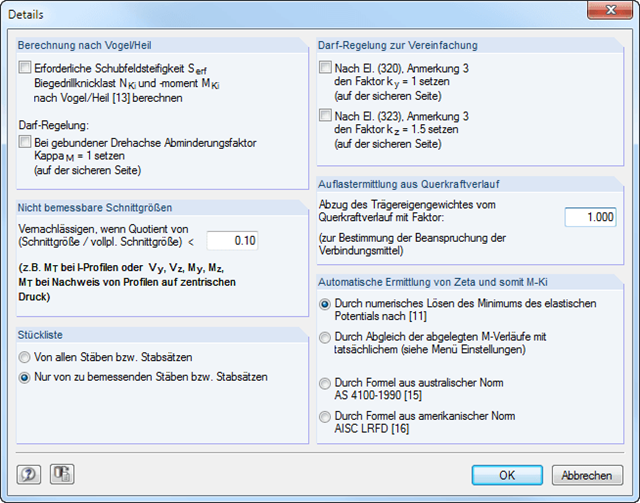
In RF‑/LTB, the design is usually performed according to the equivalent member method according to DIN 18800, Part 2. However, you can specify extensive detailed settings for the design in a separate dialog box:
Design according to Bird/Heil
Optionally, it is possible to apply the method according to Bird/Heil in the program
- the required shear stiffness Sreq
- the lateral-torsional buckling load Nki
- the critical buckling moment Mki
.
This plastic-plastic calculation method is only valid for lateral and torsional restraints with simple bending with simultaneous load introduction on the upper flange. Further requirements that must be met can be found in the program manual. In case of invalid conditions (for example, biaxial bending), RF-/LTB displays the corresponding error message. In addition, the reduction factorκM for the bending moments My can be set to 1.0 if a restrained rotation axis is present.
Non-Designable Internal Forces
It is possible to neglect non-designable internal forces and thus exclude them from the design if the quotient of the internal force and the fully plastic internal force falls below a certain value. This way, you can neglect, for example, a small moment about the minor axis, thus avoiding the method for biaxial bending.
Allowance according to DIN 18800, Part 2, Element (320) and Element (323)
Automatic determination of ζ
If you want the factor for the determination of the ideal elastic critical moment Mcr to be determined automatically, you can select one of the following types:
- Solving the elastic potential numerically
- Comparison of moment diagrams
- Australian Standard AS 4100-1990
- US standard AISC LRFD
When aligning the moment distributions, you can use the library which contains more than 600 moment distributions in tables.
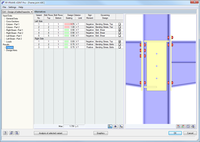
The RF-/FRAME-JOINT Pro add-on module performs the following designs according to the standards EN 1993-1-8 or DIN 18800:
- Beam end plate and column flange according to the plastic hinge theory
- Tension of bolts (including contact forces)
- Shearing of bolts
- Tension force introduction in column web and beam web
- Buckling analysis of gusset plate
- Shear design of gusset plate
- Compression force introduction in column web and buckling design of web plate
- If required:
- Design of diagonal stiffeners
- Web stiffener
- Supplementary web plates
- Compression force introduction in horizontal beam
- Design of welds