
The Concrete Design add-on allows you to design fiber-reinforced concrete components according to the guideline "DAfStb Steel Fiber-Reinforced Concrete".
You can use this option for the design according to EN 1992‑1‑1. The design according to the DAfStb guideline is carried out once the concrete of the "Fiber Concrete" type has been assigned to the reinforced structural component.
Go to Explanatory Video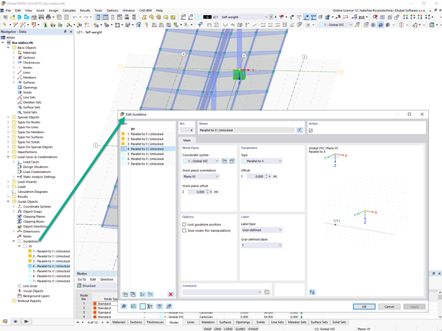
Create guidelines with or without a description for the display of a building grid! You can lock the guideline position to prevent accidental movement of them, for example.
Furthermore, you can glue the guidelines to nodes in order to move the glued nodes as well. That makes your work a lot easier!
Go to Explanatory Video
The component temperature to be applied at the design time is determined automatically. You can adjust the coefficients used to determine the temperature. In this step, it is best for you to also select the hot-dip galvanizing. According to the DASt Guideline 027 "Determination of Component Temperature of Hot-Dip Galvanized Steel Components in Case of Fire", a lower emissivity of the steel surface is applied up to a limit temperature. Overall, this gives you a lower temperature for the thus more favorable fire resistance design.
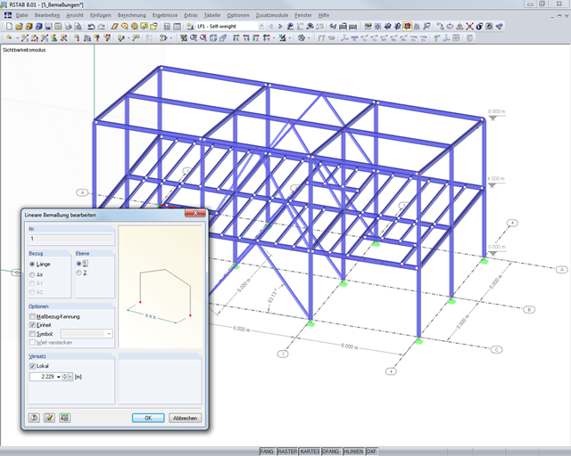
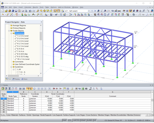
It is possible to selectively display or hide various objects such as nodes, members, supports, and others. The model can be dimensioned by using lines, arcs, inclinations, or height elevations. Freely created guidelines, sections, and comments facilitate the input and evaluation. You can also display or hide the guide objects individually.
Go to Explanatory Video
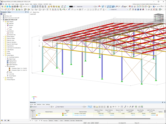
Compared to the RF‑/STEEL EC3 add-on module (RFEM 5 / RSTAB 8), the following new features have been added to the Steel Design add-on for RFEM 6 / RSTAB 9:
- In addition to Eurocode 3, other international standards are integrated (such as AISC 360, CSA S16, GB 50017, SP 16.13330)
- Consideration of hot-dip galvanizing (DASt guideline 027) in the fire protection design according to EN 1993‑1‑2
- Input option for transverse stiffeners that can be taken into account in the shear buckling analysis
- Lateral-torsional buckling can also be checked for hollow sections (for example, relevant for slender, high rectangular hollow sections)
- Automatic detection of members or member sets valid for the design (for example, automatic deactivation of members with invalid material or members already contained in a member set)
- Design settings can be adjusted individually for each member
- Graphical display of the results in the gross section or the effective section
- Output of the used design check formulas (including a reference to the used equation from the standard)

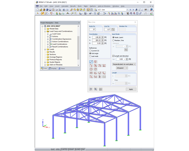
There are various tools, such as the object snap, user‑defined input grids, and guidelines, that facilitate the graphical input of structural data. Import DXF files as a line model in order to use specific snap points.
Work more efficiently by freely adjusting the display of your model. You can selectively display or hide various objects, such as nodes, members, supports, and others. Dimension your model by using lines, arcs, inclinations, or height elevations. Freely created guidelines, sections, and comments facilitate you the input and evaluation. You can also display or hide the guide objects individually.
Go to Explanatory Video
SHAPE-THIN includes an extensive library of rolled and parameterized cross-sections. They can be composed or supplemented by new elements. It is possible to model a section consisting of different materials.
Graphical tools and functions allow for modeling complex section shapes in the usual way common for CAD programs. The graphical entry provides the option of setting point elements, fillet welds, arcs, parameterized rectangular and circular sections, ellipses, elliptical arcs, parabolas, hyperbolas, spline, and NURBS. Alternatively, it is possible to import a DXF file that is used as the basis for further modeling. You can also use guidelines for modeling.
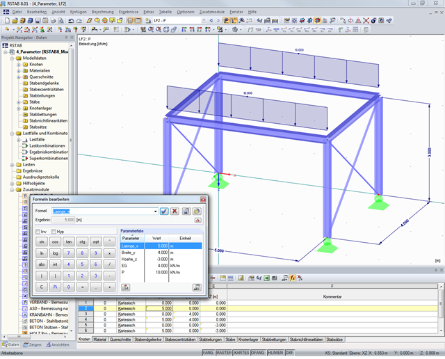
Furthermore, parameterized input allows you to enter model and load data in a specific way so they depend on certain variables.
Elements can be divided or attached to other objects graphically. SHAPE-THIN automatically divides the elements and provides for an uninterrupted shear flow by introducing dummy elements. In the case of dummy elements, you can define a specific thickness to control the shear transfer.
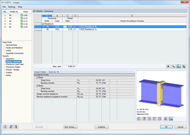
After the design, all results are displayed in clearly arranged result tables; for example, by load case or by node. The governing internal forces are compared with the limit values listed in the DSTV guideline.
You can visualize the joints graphically in the add-on module or in RFEM/RSTAB. In addition to the input and result data, including design details displayed in tables, you can add all graphics into the printout report. This way, comprehensible and clearly arranged documentation is guaranteed.
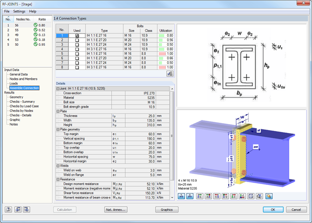
The extensive DSTV guideline is included in the database of the RF-/JOINTS Steel - DSTV add-on module. Each joint is characterized by a unique alphanumeric code.
The possible DSTV connections can be filtered out by the corresponding specifications for the DSTV connection type (IH, IW, IS, IG, and IK) and the used cross-section. This way, it is possible to determine the load-carrying capacity of the selected joint.
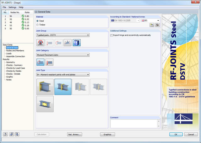
After opening the add-on module, it is necessary to select the joint type (moment resistant or pinned I-beam connection). You can select the individual nodes graphically in the RFEM/RSTAB model.
The RF-/JOINTS Steel - DSTV add-on module recognizes the cross-section including the corresponding material automatically, and checks if a joint design according to the DSTV guideline is possible. Furthermore, you can model and design structurally similar connections on several locations in the beam structure.
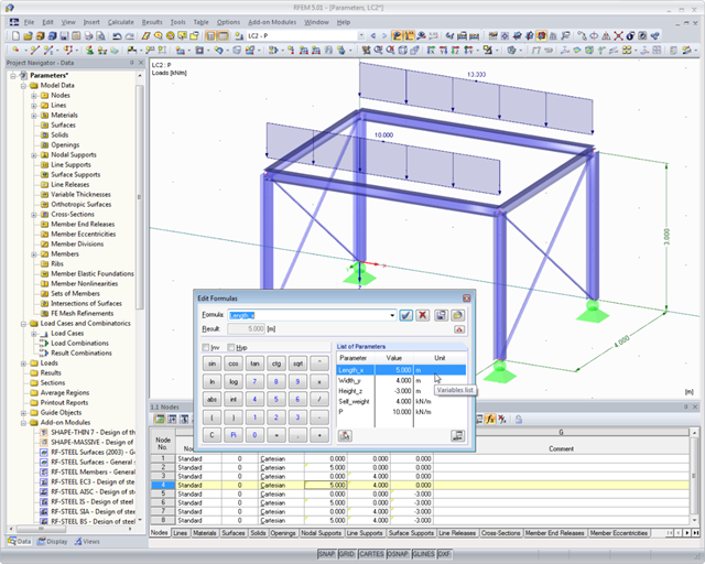
In order to work with recurring structural systems efficiently, RFEM provides the parameterized input, which can be combined with a parameterizable guideline method. Models can be created using particular parameters and adjusted to a new situation by modifying the parameters.
There are various tools such as the object snap, user‑defined input grids, and guidelines, that facilitate the graphical input of structural data. DXF files can be imported as line models or used as a layer in the background in order to use specific snap points.
Customize your model to work even more efficiently. You can selectively display or hide various objects, such as nodes, members, supports, and others. The model can be dimensioned by using lines, arcs, inclinations, or height nodes. Freely createable guidelines, sections, and comments facilitate you the input and evaluation. You can also display or hide the guide objects individually.
It is possible to selectively display or hide various objects such as nodes, members, supports, and others. You can dimension the model by using lines, archs, inclinations, or height elevations. Freely created guidelines and comments facilitate the input and evaluation. You can also display or hide the guide objects individually.
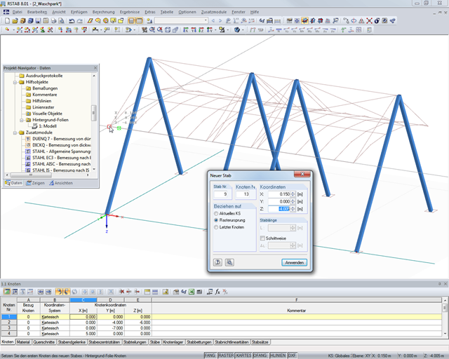
There are various tools such as the object snap, user‑defined input grids, and guidelines, that facilitate the graphical input of structural data. DXF files can be imported as line models or used as a layer in the background in order to use specific snap points.
For efficient editing of recurring systems, RFEM provides parameterized input, which can be combined with a parameterizable guideline method. Models can be created using particular parameters and adjusted to a new situation by modifying the parameters.