
In this tutorial, we would like to inform you about the essential features of the RFEM program. The first part shows how to create the structural objects and loads, combine the loads, perform a structural analysis, check the results, and prepare the data for printing. Eurocodes with the CEN settings are used as standards.
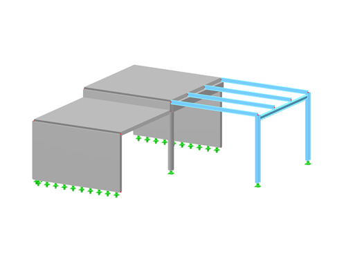
In this tutorial, we would like to inform you about the essential features of the RFEM program. The first part shows how to create the structural objects and loads, combine the loads, perform a structural analysis, check the results, and prepare the data for printing. The US codes are used as standards.
The Timber Design add-on allows you to design timber members and surfaces according to various design standards. Cross-section resistance checks, stability analyses, and serviceability limit state design checks can also be performed. The input and result evaluation are completely integrated in the user interface of the structural FEA software RFEM and the frame & truss analysis software RSTAB.
This manual describes the Timber Design add-on for the RFEM 6 and RSTAB 9 programs.
The Masonry Design add-on activates special material models that have been developed for calculating masonry structures. This allows you to consider the masonry material in an FEM analysis.
In the calculation, internal forces and deformations are determined on the basis of stress-strain lines derived from the standardization. This means that the design is based on the standard.
This manual describes the Masonry Design add-on for the RFEM 6 program.
The Aluminum Design add-on allows you to design aluminum members according to various design standards. It is possible to perform cross-section resistance checks, stability analyses, and serviceability limit state design checks. The input and result evaluation are completely integrated in the user interface of the structural FEA software RFEM and the frame & truss analysis software RSTAB.
This manual describes the Aluminum Design add-on for the RFEM 6 and RSTAB 9 programs.
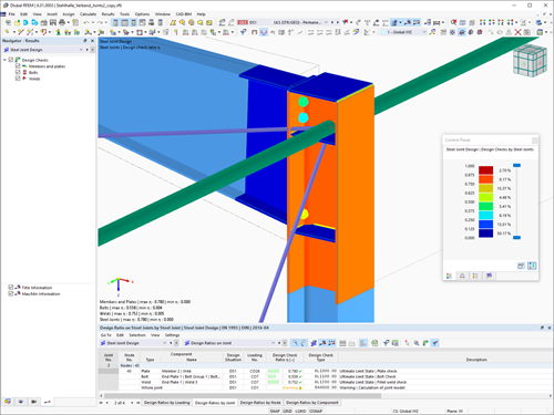
The "Steel Joints" add-on allows for the analysis of connections on the basis of an FE model. The design checks are carried out for various connection types for rolled and welded cross-sections. The input and result evaluation are completely integrated in the user interface of the structural FEA software RFEM.
This manual describes the Steel Joints add-on for RFEM 6.
In this tutorial, we would like to inform you about the essential features of the RFEM program. In the first part, a model was defined and a structural analysis carried out. Then the concrete and steel designs were performed in the following parts. This part now deals with the design of the steel connections according to EN 1993-1-8 with the CEN settings.
The Construction Stages Analysis (CSA) add-on allows you to represent the construction process of the model in the RFEM 6 program. In this way, you can add, remove, or adjust structural objects to the individual construction phases. Furthermore, you can use the add-on can to determine the sequence of the load application and the way how the load cases are combined within the construction stages.
In this tutorial, we would like to inform you about the essential features of the RFEM program. In the first part, a model was defined and a structural analysis carried out. Then the concrete and steel designs were performed in the following parts. This part now deals with the design of the steel connections according to AISC 360-22.
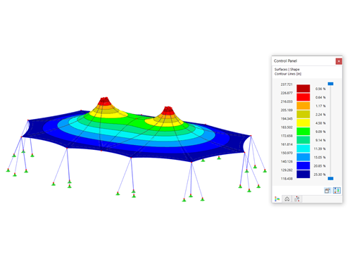
The Form-Finding add-on finds the optimal shape of members subjected to axial forces and tension-loaded surface models. The shape is determined by the equilibrium between the member axial force or the membrane stress and the existing boundary conditions.
The resulting new model shape with impressed force conditions is made available as a universally applicable initial state for further calculation of the entire structure.
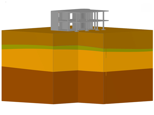
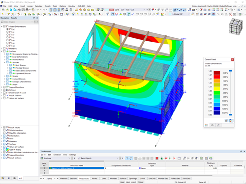
The Geotechnical Analysis add-on allows for a finite element analysis of soil solids with the suitable material laws in RFEM 6. By integrating Geotechnical Analysis into the FEA software, the soil-structure interaction can be represented computationally completely in the overall model.
With the Geotechnical Analysis, it is possible to determine the stresses and deformations of a soil solid. The input and result evaluation are integrated in the user interface of the RFEM 6 program.
This manual describes the Geotechnical Analysis add-on for the RFEM 6 program.
The Multilayer Surfaces Add-on allows you to define the layer structure of any material models. In the case of orthotropic materials, the individual layers can be rotated by an angle β, and thus it is possible to consider different stiffnesses by direction. The Multilayer Surfaces add-on is completely integrated in the user interface of the FEA program RFEM.
This manual describes the Multilayer Surfaces add-on for the RFEM 6 program.
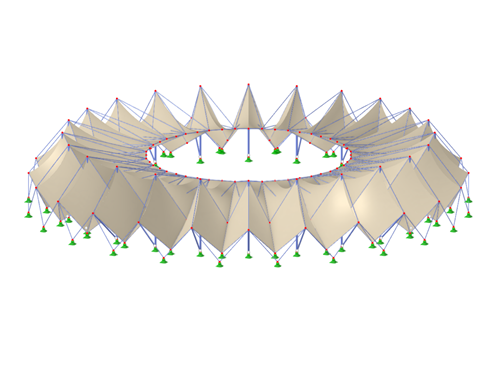
This manual describes the modeling of a stadium roof made of membranes in RFEM 6. Since the model consists of several segments, the creation of the individual segments is shown. Each segment consists of a main structure (a column, a stiffening element, cables) and a secondary structure (a membrane).
This manual describes the topics of the webinar "Masonry Design of Using Finite Element Method in RFEM 6".
This webinar shows you how to model masonry structures in RFEM 6 and how to calculate them using the nonlinear orthotropic material model.
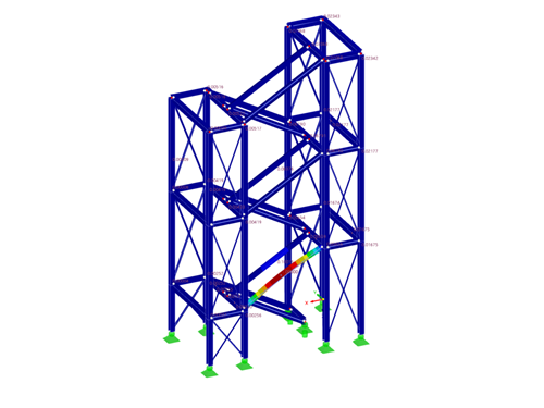
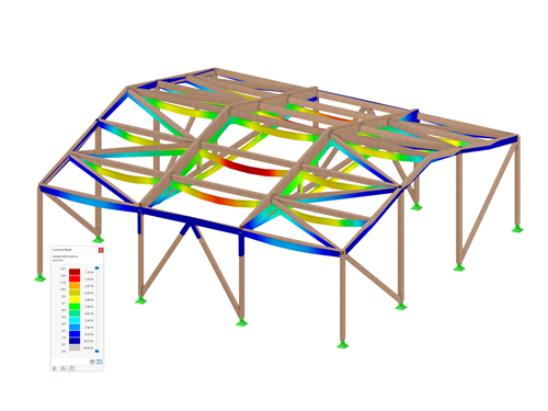
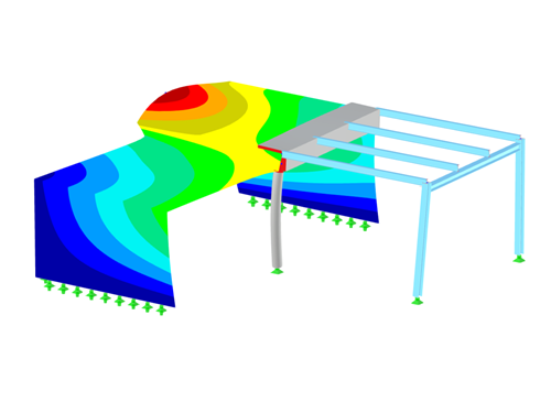
This manual describes the topics of the webinar "Stability and Warping Torsion Analyses in RFEM 6 and RSTAB 9".
In the webinar, a stability analysis of a staircase tower is carried out. It explains when and why a warping torsion analysis with 7 degrees of freedom is necessary. Furthermore, special attention is given to how you can create and combine local imperfections in RFEM 6 and RSTAB 9.
In the manual, all steps are carried out in RFEM 6, but the same also applies to RSTAB 9.
In this tutorial, we would like to inform you about the essential features of the RFEM program. In the first part, a model was defined and a structural analysis carried out. Then the concrete and steel designs were performed out in the following parts. This part now guides you through the dynamic analysis of the model according to EN 1998-1 with the CEN settings.