In this tutorial, we would like to inform you about the essential features of the RFEM program. In the first section, a model was defined and a structural analysis carried out. Then the concrete and steel designs were performed in the following sections. This section now deals with the design of the steel connections according to EN 1993-1-8 with the CEN settings.
Online Manuals
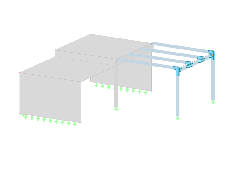
RFEM 6 | Tutorial – Steel Joints