As described in Chapter Computational Mesh and Model Simplification, two types of meshes are used for the simulation. The simplified model is "shrink-wrapped" by a mesh of the boundaries, which again provides the basis of the 3D volume mesh around it. The former represents the "Surface Mesh," the latter the "Volume Mesh."
When the calculation of results is started (see Chapter Calculation), the mesh is created automatically. To create the mesh separately, however, select "Generate Mesh" on the "Simulation" menu.
The "Edit Simulation" button
![]() provides specific options to display the two types of meshes.
provides specific options to display the two types of meshes.
Show Surface Mesh
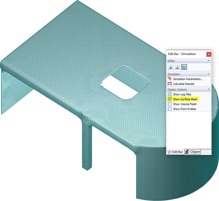
Select this option to check whether the "Mesh Density" set in the dialog box gives an adequate representation of the original model. Furthermore, the "Level of Detail" set in the Edit Model dialog box strongly influences the quality of the surface mesh. If the simplified model appears too coarse or extremely fine, you should modify the level of detail.
In the "View Navigator," you can control the display of "Mesh Faces" (the filled mesh surfaces) and "Mesh Edges" (separation lines between mesh elements) – see Image 4.1 .
Show Volume Mesh

The volume mesh can be displayed in a "Slicer plane." It gives a section through the wind tunnel that is parallel to one of the global planes (XY, YZ, XZ). For more information on handling the tool, see Chapter Slicer. You can distinguish between the refined volume mesh at the model boundaries and the wider mesh at distant locations.