8 Results
View Results:
Sort by:
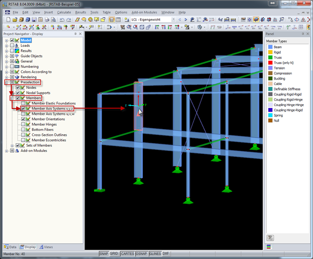
The local coordinate system of a member is particularly important when defining member end releases and member nonlinearities. The definitions follow the orientation of the axes. You can temporarily adjust the visibility of these member axes by means of preselection.
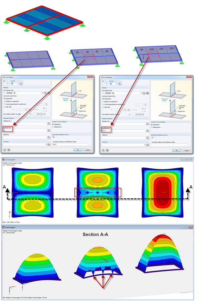
The following post describes two different types of line release definitions.
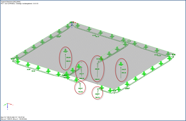
The boundary conditions of a plate support can be entered quickly as singular and line supports in the FEA software. However, if the flexibility of the supports is not considered when modeling the structure, it is often necessary to take a closer look at the support definitions during the design using stresses or the determination of the required reinforcement, at the latest.
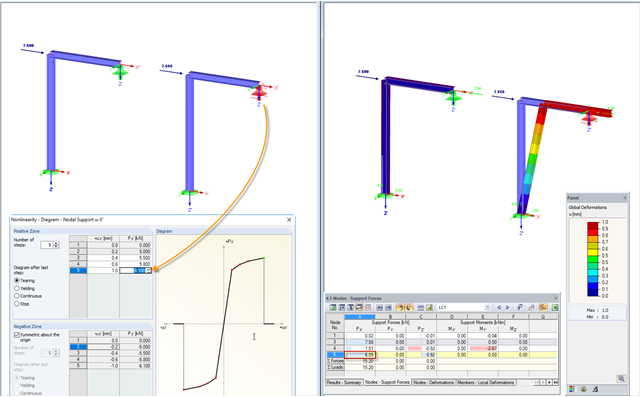
RFEM and RSTAB provide numerous options for nonlinear definitions of nodal supports. With regard to an earlier article, further possibilities of the nonlinear support design for a movable support are shown in a simple example in this article. For a better understanding, the result is always compared to a linearly defined support.

When using the RF‑GLASS add‑on module, you can define just the geometry in the main program, as well as the load situation of the structural component to be designed. The respective support conditions and all further design-relevant definitions (for example, the layer structure and support conditions), can be further specified in RF‑GLASS.
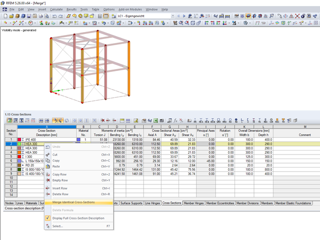
When modeling more complex structures with an increased degree of repetition, identical material and cross-section definitions often occur.

In the RF-GLASS add-on module, 3D rendering is implemented to facilitate the definition of the support conditions. This interactive graphical visualization facilitates the input and control of line and nodal supports. However, the schematic display can also be selected, if necessary.

The additional loads from self‑weight are usually composed of several layers; for example, classic floor and ceiling layers in buildings, or road coatings for bridge constructions. When defining load definitions in RFEM and RSTAB, you can use the multi-layer load to define the individual layers with thickness and specific weight.