


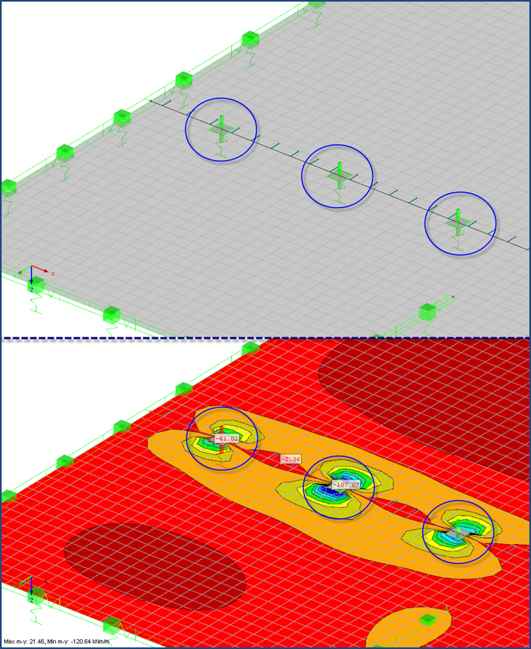
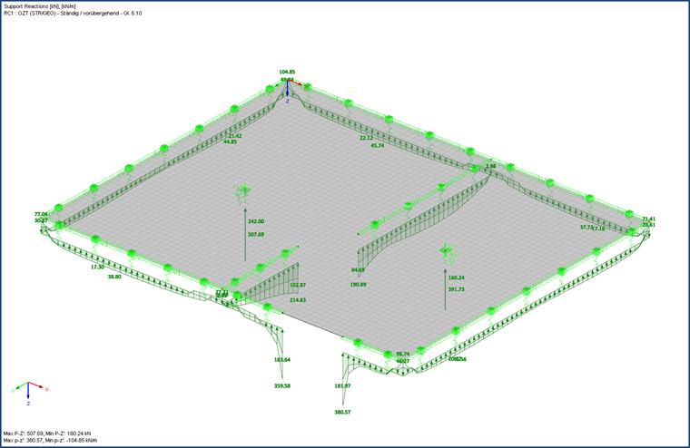
While the results at locations (except the discontinuity location) are ever more precise with an increasingly refined FE mesh and barely change in the end, the result values at the nodal support and the ends of the line supports are constantly increasing. Usually, the consequences of this are non-designable locations or very high results. Therefore, it is necessary either to argue these singularities or specify the boundary conditions more precisely.
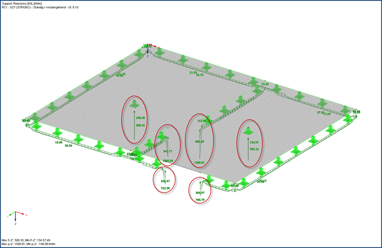
Nodal Supports
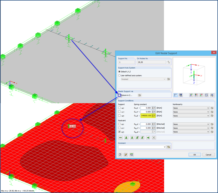
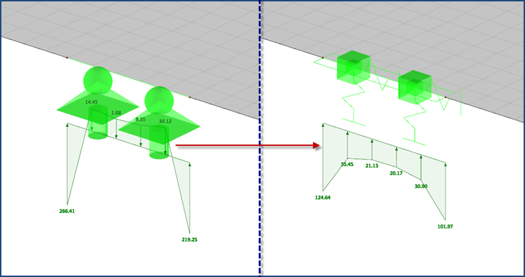
If there is a column under the plate, it is defined as a nodal support in 2D modeling. In order to avoid singular supports in an FE node with rigid supports, you can either enter spring constants manually or determine the foundation coefficients automatically using the "Column in Z" option.
An elastic support can be considered automatically by setting a few parameters.
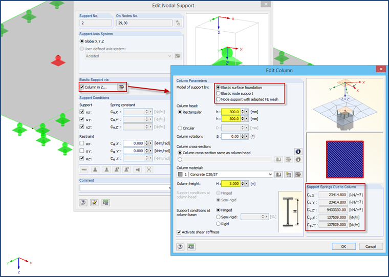
In this case, there are three options:
- Elastic surface foundation: In the program, an elastic surface foundation is taken into account with the column dimensions. However, this option inevitably causes the column head to be partially restrained by vertical force pairs such as support springs in the x- and y-directions.
- Elastic nodal support: For stiffness increased via the column, a surface with double plate thickness is applied for the calculation and singularly supported with the determined spring constants.
- Nodal support with adjusted FE mesh: A double thickness is also applied internally here. However, the support is carried out as a rigid support in Z.
The last two options allow you also to use a hinged or semi-rigid support at the column head, and all three options allow you to use a hinged, semi-rigid, or rigid support at the column base.
The determined spring constants are displayed directly on the right side below the graphics, reflecting all changes. Furthermore, there is the option to consider a different column head cross-section as well as the shear stiffness of the column. The shear stiffness is activated by default. It reduces the horizontal support springs as well as the rotational springs of the support.
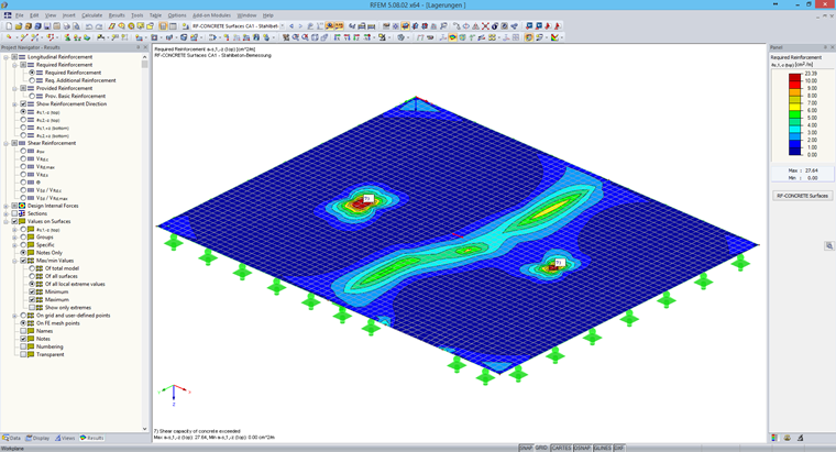
For all three options, the column cross-section is taken from the design of surfaces performed in the add-on modules, such as RF-STEEL Surfaces, RF-CONCRETE Surfaces, or RF-LAMINATE. Thus, the design always applies the connection internal forces, which leads to more economical results.
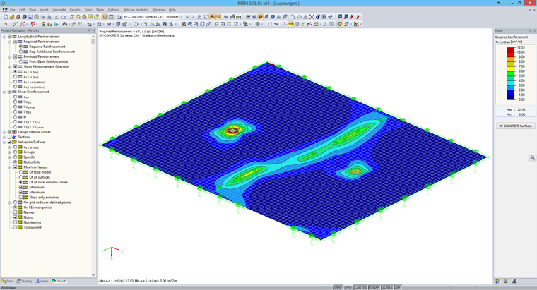
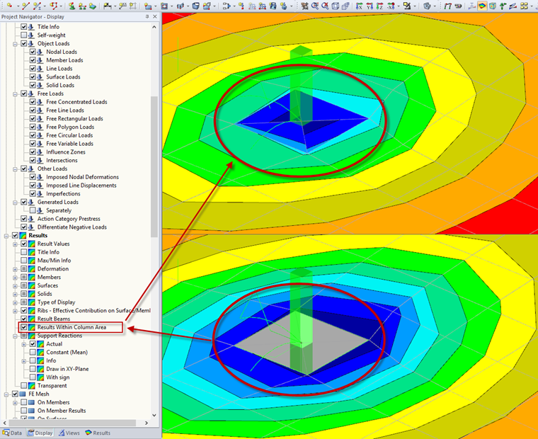
Also, the results within the column area are not displayed in RFEM. However, if these are required, you can activate the corresponding check box in the Results Navigator.
If there is a hinged connection of two plates (via a line release) over the nodal supports, note the following: Due to the internal consideration of an additional surface, the line release is suspended and thus no restraining moments arise on the plate edges.
This can only be avoided by either suspending one of the surfaces in front of the "columns", or by selecting a "normal" elastic hinged nodal support. If the elastic nodal support is selected and the parameters are specified when defining the column, you can simply open the "Edit Nodal Support" dialog box and disable the "Column in Z" option. Thus, the previously determined spring constants are taken automatically.
Line Supports
If the plate is supported on walls, it is defined as a line support in 2D modeling. In the finite element analysis, the line support is internally divided into the nodal supports at each FE-mesh point. The program then determines the support force for each nodal support. A linear distribution between the individual support points is created using smoothing options that allow consideration of the influence of the adjacent nodal supports. To also avoid overly high peak values in the case of line supports, you can select the "Wall in Z" option.
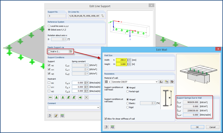
In the case of wall pillars in particular, the qualitative distribution of support reactions, taking into account the elasticity, can be very different.
In contrast to the nodal supports as columns, the results within the column area are not hidden for the line supports of a wall.