


General
Each nodal support has its own local axis system. The axes are defined as X', Y', and Z'. By default, this support axis system is based on the global axis system of the RFEM or RSTAB file. However, it is possible to define a custom axis system or simply a rotation. In the example shown here, the support axis systems are displayed for all nodal supports. The options of the individual nonlinearities are shown for the displacement in X'. Similar definitions apply for the other two support axis directions.
Note: The nonlinearity always refers to the acting support force.
Diagram: Tearing
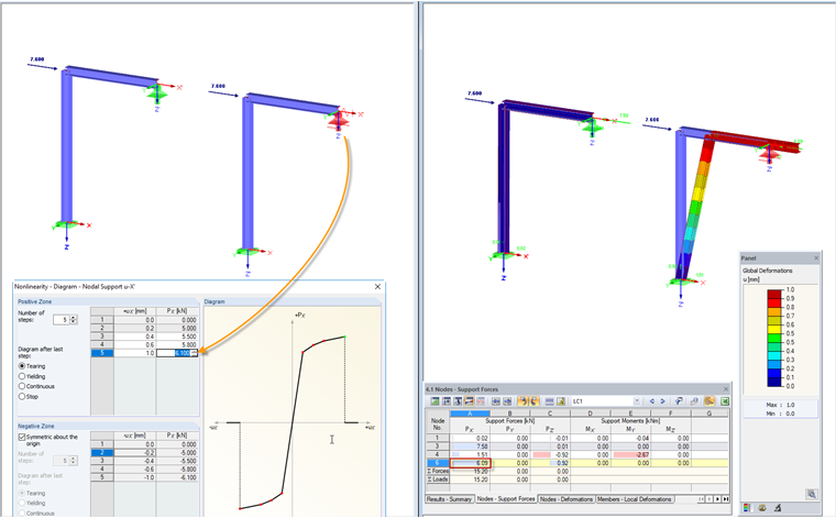
In the diagram, the load-deformation behavior of a support can be reproduced very close to the reality. In the case of “yielding”, the support fails after reaching the greatest positive or the smallest negative support force. The positive and negative zones can also be defined independently of each other. In Figure 01, the acting load was selected in such a way as to represent the state shortly before reaching the tearing.
Diagram: Yielding
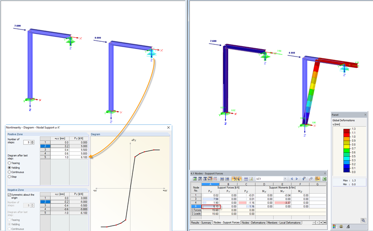
If the defined deformation is reached, the support force no longer rises in further load increments. This state is referred to as “yielding”. The deformation can increase, but the support force does not exceed the maximum value defined. It is also possible to specify this differently for the positive and negative zones.
Diagram: Continuous
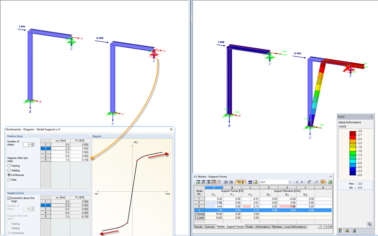
After reaching the maximum deformation defined, the support force and the deformation continue to increase linearly. The ratio is defined by the gradient of the straight line, described by the last two diagram entries.
Diagram: Stop
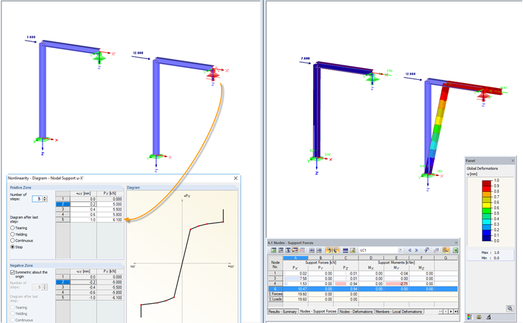
As of the deformation greater than the last value in the diagram, the support's effect is full. The node is then preserved completely for the defined direction.
Friction PY'
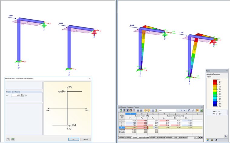
In this case, the support definition takes into account the support force acting in the direction Y'. By defining the friction coefficient, the maximum value of the support force in X' relating to the support force in Y' is set.
Friction PZ'
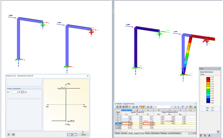
The support definition takes into account the support force acting in the direction Z'. By defining the friction coefficient, the maximum value of the support force in X' relating to the support force in Z' is set.
Friction PY'PZ'
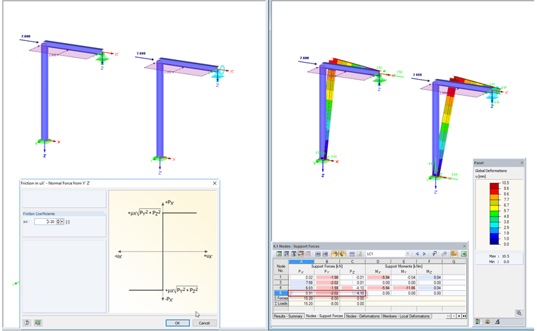
This option allows you to model the support using the vector of PY' and PZ' as well as the friction coefficient.
Friction PY'+PZ'
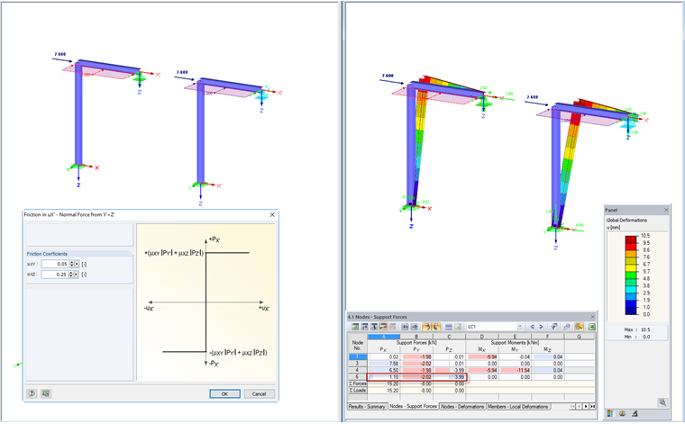
If the support is designed in such a way that the friction coefficient is different for Y' and Z', you can use this support definition. The respective support force is multiplied by the specified friction coefficient, and both components are then added together to form the governing support in X'.