6 Results
View results:
Sort by:

Creating a validation example for Computational Fluid Dynamics (CFD) is a critical step in ensuring the accuracy and reliability of simulation results. This process involves comparing the outcomes of CFD simulations with experimental or analytical data from real-world scenarios. The objective is to establish that the CFD model can faithfully replicate the physical phenomena it is intended to simulate. This guide outlines the essential steps in developing a validation example for CFD simulation, from selecting a suitable physical scenario to analyzing and comparing the results. By meticulously following these steps, engineers and researchers can enhance the credibility of their CFD models, paving the way for their effective application in diverse fields such as aerodynamics, aerospace, and environmental studies.

CFD calculations are in general very complex. An accurate calculation of wind flow around complicated structures is very demanding on time and computational costs. In many civil engineering applications, high accuracy is not needed and our CFD program RWIND 2 enables in such cases to simplify the model of a structure and reduce the costs significantly. In this article, some questions about the simplification are answered.

The size of the computational domain (wind tunnel size) is an important aspect of wind simulation that has a significant impact on the accuracy as well as the cost of CFD simulations.

In RFEM and RSTAB, you can use many interfaces to simplify the modeling of your structure. From background layers, to the import of IFC objects that can be converted into members or surfaces, to the import of the entire structural system from Revit or Tekla. Regardless of the performance of the selected interface, further utilization also depends on the accuracy of the imported data.
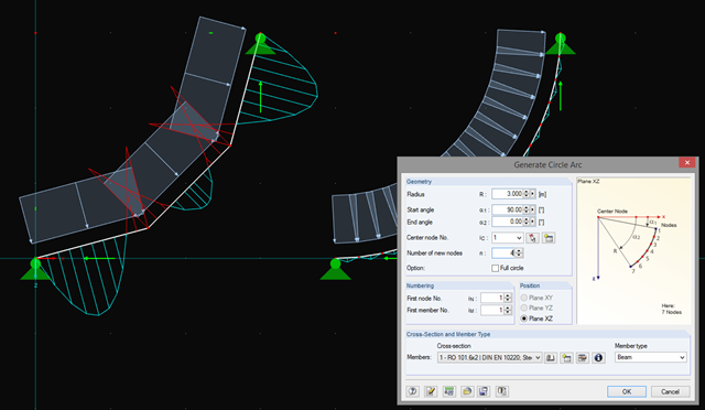
In addition to straight beams, it is sometimes necessary to calculate or design arched or circular beams in RSTAB. For this purpose, there is a special feature under "Tools" → "Generate Model – Members" → "Circle". You can easily use this tool to generate a full or pitch circle. The most important parameter here is the number of new nodes, which affects the accuracy of the results.
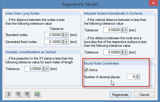
During the cooperation between the structural and design engineers, the DXF format is often used if there is no direct interface. However, the geometrical data of these DXF files are not always accurate. For example, an inaccuracy in the third decimal place is not noticeable, but it can lead to numerical problems when generating the FE mesh in RFEM.