


Experience from our support activities has shown that modeling inaccuracies occur more frequently when using background layers in particular, or they are already imported into the structure. Larger gaps in the structure resulting primarily from the conversion of solid models into members or surfaces are usually obvious. However, if the node coordinates deviate only minimally from each other, which is often the case with modeling methods using background layers due to the large number of snap points, the search is usually a little more time-consuming. The features of the model check are usually helpful in these cases.
A special function that appears in the model check for "Identical Nodes", as well as under "Regenerate Model", is the unification of close-lying nodes. This will be considered in more detail below.
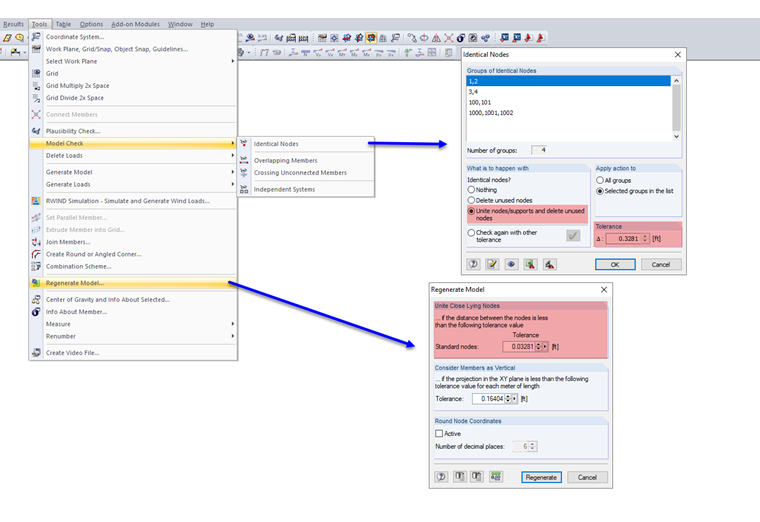
Basically, the function is clear: If the distance between two nodes is smaller than the specified tolerance, they are united. To illustrate the functionality, we define the nodes as shown in Image 02 on the left. Likewise, each node gets a nodal load so that the effect of the unification becomes clearer.
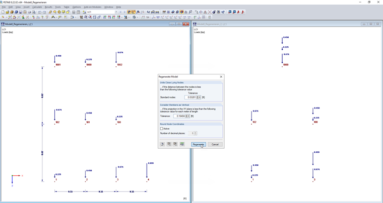
The horizontal distance is 0.1 m in each case. If the regeneration is now carried out with a tolerance greater than or equal to 0.1 m, the nodes are united (Image 02, right).
It becomes apparent that the numbering of the nodes determines which of the nodes is moved or deleted. In the bottom row, Node 1 is the initial node due to having the lowest number. Based on this, the program searches for further nodes in the defined tolerance. Node 2 is included and is united with Node 1. Node 3 remains in its original location because Node 2 is no longer available and the distance to Node 1 is greater than the tolerance. Similarly, starting from Node 3, the program searches for further nodes. Thus, Node 4 is unified with Node 3.
To prove that the coordinates do not determine the prioritization, the order in Row 2 has been changed. The middle node has been combined with the right node. In the top row, the initial node is in the middle. As a result, both the adjacent nodes are united with the middle one.
Thus, the logic behind it is clarified. What consequences does this have for the application in the real case? These inaccuracies are relatively common when connecting bracing to the rest of the structure. This case is shown in simplified form in the following image.
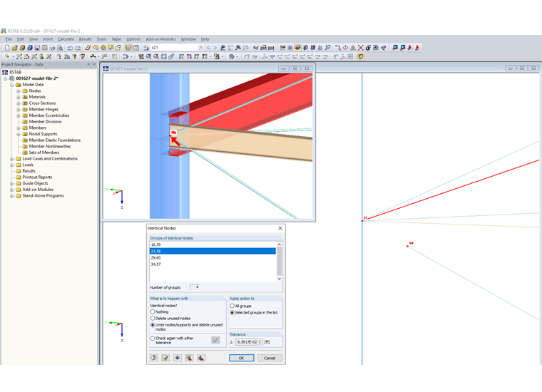
By using the model check of the identical nodes, you can find such inaccuracies and correct them with the corresponding tolerance setting. To use the feature as intended, you can display the node number. Only then can it be ensured that the diagonal is applied to the frame corner, and not that the column, including the beam, is inclined. The process is also shown again in the corresponding video.
