
Using the "Damper" member type, you can define a damping coefficient, a spring constant, and a mass. This member type extends the possibilities within the Time History Analysis.
With regard to viscoelasticity, the "Damper" member type is similar to the Kelvin-Voigt model, which consists of the damping element and an elastic spring (both connected in parallel).

The "Spring" member type is used to simulate linear and nonlinear spring properties via a linear object. This input function helps you to model the stiffness specifications in the force/displacement unit.
Go to Explanatory Video
Compared to the RF-/STEEL Warping Torsion add-on module (RFEM 5 / RSTAB 8), the following new features have been added to the Torsional Warping (7 DOF) add-on for RFEM 6 / RSTAB 9:
- Complete integration into the environment of RFEM 6 and RSTAB 9
- 7th degree of freedom is directly taken into account in the calculation of members in RFEM/RSTAB on the entire system
- No more need to define support conditions or spring stiffnesses for calculation on the simplified equivalent system
- Combination with other add-ons is possible, for example for the calculation of critical loads for torsional buckling and lateral-torsional buckling with stability analysis
- No restriction to thin-walled steel sections (it is also possible to calculate ideal overturning moments for beams with massive timber sections, for example)
- Consideration of 7 local deformation directions (ux, uy, uz, φx, φy, φz, ω) or 8 internal forces (N, Vu, Vv, Mt,pri, Mt,sec, Mu, Mv, Mω) when calculating member elements
- Usable in combination with a structural analysis according to linear static, second-order, and large deformation analysis (imperfections can also be taken into account)
- In combination with the Stability Analysis add-on, allows you to determine critical load factors and mode shapes of stability problems such as torsional buckling and lateral-torsional buckling
- Consideration of end plates and transverse stiffeners as warping springs when calculating I-sections with automatic determination and graphical display of the warping spring stiffness
- Graphical display of the cross-section warping of members in the deformation
- Full integration with RFEM and RSTAB
You can perform the calculation of the warping torsion on the entire system. Thus, you consider the additional 7th degree of freedom in the member calculation. The stiffnesses of the connected structural elements are automatically taken into account. It means, you don't need to define equivalent spring stiffnesses or support conditions for a detached system.
You can then use the internal forces from the calculation with warping torsion in the add-ons for the design. Consider the warping bimoment and the secondary torsional moment, depending on the material and the selected standard. A typical application is the stability analysis according to the second-order theory with imperfections in steel structures.
Did you know that The application is not limited to thin-walled steel cross-sections. Thus, it is possible for you, for example, to perform the calculation of the ideal overturning moment of beams with solid timber cross-sections.
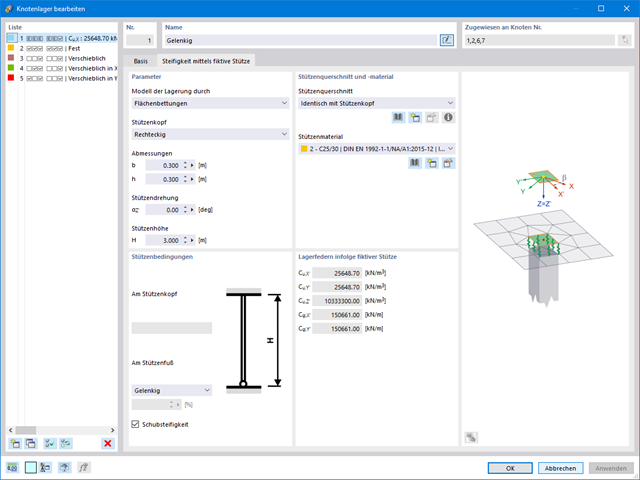
If you are working with nonlinearities, this feature is suited very well to support you. For example, you can specify nonlinearities of member end releases (yielding, tearing, slippage, and so on) and supports (including friction). Furthermore, you can use special dialog boxes to determine the spring stiffnesses of columns and walls based on the geometry specifications.
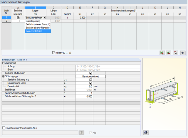
In STEEL AISC, it is possible to consider lateral intermediate supports at any location. For example, it is possible to stabilize only the upper flange.
Furthermore, user-defined lateral intermediate supports can be assigned; for example, single rotational springs and translational springs at any location at the cross-section.
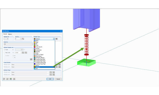
The member type 'Dashpot' can be used for time history analyzes in RFEM/RSTAB with the add-on modules RF-/DYNAM Pro - Forced Vibrations and RF-/DYNAM Pro - Nonlinear Time History. This linear viscous damping element considers forces dependent on velocity.
With regard to viscoelasticity, the member type 'Dashpot' is similar to the Kelvin-Voigt model, which consists of the damping element and an elastic spring (both connected in parallel).

- Import of materials, cross-sections, and internal forces from RFEM/RSTAB
- Steel design of thin‑walled cross‑sections according to EN 1993‑1‑1:2005 and EN 1993‑1‑5:2006
- Automatic classification of cross-sections according to EN 1993-1-1:2005 + AC:2009, Cl. 5.5.2, and EN 1993-1-5:2006, Cl. 4.4 (cross-section class 4), with optional determination of effective widths according to Annex E for stresses under fy
- Integration of parameters for the following National Annexes:
-
 DIN EN 1993-1-1/NA:2015-08 (Germany)
 -
 ÖNORM B 1993-1-1:2007-02 (Austria)
 -
 NBN EN 1993-1-1/ANB:2010-12 (Belgium)
 -
 BDS EN 1993-1-1/NA:2008 (Bulgaria)
 -
 DS/EN 1993-1-1 DK NA:2015 (Denmark)
 -
 SFS EN 1993-1-1/NA:2005 (Finland)
 -
 NF EN 1993-1-1/NA:2007-05 (France)
 -
 ELOT EN 1993-1-1 (Greece)
 -
 UNI EN 1993-1-1/NA:2008 (Italy)
 -
 LST EN 1993-1-1/NA:2009-04 (Lithuania)
 -
 UNI EN 1993-1-1/NA:2011-02 (Italy)
 -
 MS EN 1993-1-1/NA:2010 (Malaysia)
 -
 NEN EN 1993-1-1/NA:2011-12 (Netherlands)
 - NS EN 1993-1-1/NA:2008-02 (Norway)
-
 PN EN 1993-1-1/NA:2006-06 (Poland)
 -
 NP EN 1993-1-1/NA:2010-03 (Portugal)
 -
 SR EN 1993-1-1/NB:2008-04 (Romania)
 -
 SS EN 1993-1-1/NA:2011-04 (Sweden)
 -
 SS EN 1993-1-1/NA:2010 (Singapore)
 -
 STN EN 1993-1-1/NA:2007-12 (Slovakia)
 -
 SIST EN 1993-1-1/A101:2006-03 (Slovenia)
 -
 UNE EN 1993-1-1/NA:2013-02 (Spain)
 -
 CSN EN 1993-1-1/NA:2007-05 (Czech Republic)
 -
 BS EN 1993-1-1/NA:2008-12 (the United Kingdom)
 -
 CYS EN 1993-1-1/NA:2009-03 (Cyprus)
 - In addition to the National Annexes (NA) listed above, you can also define a specific NA, applying user‑defined limit values and parameters.
- Automatic calculation of all required factors for the design value of flexural buckling resistance Nb,Rd
- Automatic determination of the ideal elastic critical moment Mcr for each member or set of members on every x-location according to the Eigenvalue Method or by comparing moment diagrams. You only have to define the lateral intermediate supports.
- Design of tapered members, unsymmetric sections or sets of members according to the General Method as described in EN 1993-1-1, Cl. 6.3.4
- In the case of the General Method according to Cl. 6.3.4, optional application of "European lateral-torsional buckling curve" according to Naumes, Strohmann, Ungermann, Sedlacek (Stahlbau 77 [2008], pp. 748‑761)
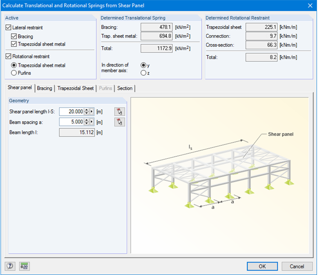
- Rotational restraints can be taken into account (trapezoidal sheeting and purlins)
- Optional consideration of shear panels (for example, trapezoidal sheeting and bracing)
- RF-/STEEL Warping Torsion module extension (license required) for stability analysis according to the second-order analysis as stress analysis including consideration of the 7th degree of freedom (warping)
- Module extension RF-/STEEL Plasticity (license required) for plastic analysis of cross‑sections according to Partial Internal Forces Method (PIFM) and Simplex Method for general cross‑sections (in connection with the RF‑/STEEL Warping Torsion module extension, it is possible to perform the plastic design according to the second‑order analysis)
- Module extension RF-/STEEL Cold-Formed Sections (license required) for ultimate and serviceability limit state designs for cold-formed steel members according to the EN 1993-1-3 and EN 1993-1-5 standards
- ULS design: Selection of fundamental or accidental design situations for each load case, load combination, or result combination
- SLS design: Selection of characteristic, frequent, or quasi-permanent design situations for each load case, load combination, or result combination
- Tension analysis with definable net cross-section areas for member start and end
- Weld designs of welded cross-sections
- Optional calculation of warp spring for nodal support on sets of members
- Graphic of design ratios on cross-section and in RFEM/RSTAB model
- Determination of governing internal forces
- Filter options for graphical results in RFEM/RSTAB
- Representation of design ratios and cross‑section classes in the rendered view
- Color scales in result windows
- Automatic cross-section optimization
- Transfer of optimized cross-sections to RFEM/RSTAB
- Parts lists and quantity surveying
- Direct data export to MS Excel
- Verifiable printout report
- Possibility to include the temperature curve in the report
Dlubal_KohlA.png?mw=640&hash=b61610e3d99aeebcfe7fbaf861e7f24b463f4458)
- Design of the following Sikla joints:
- Brackets of type AK and TKO
- End plates of type STA, WBD, and WD
- Interaction of internal forces
- Considering Eccentricities
- Determination of nonlinear spring constants
- Automatic check of connection geometry
- Check of connected girder cross‑sections
- Documentation of available loading and comparison with resistances
- Results of design ratio for each individual joint
- Automatic determination of governing internal forces for several load cases and connection nodes
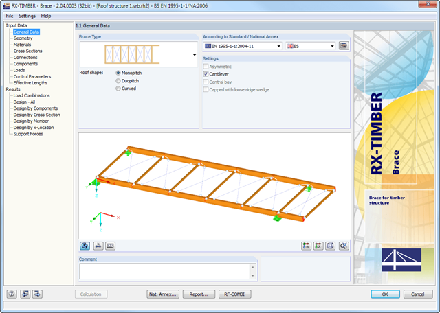
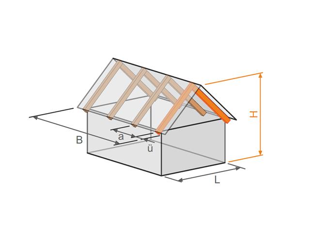
The geometry is entered by means of templates, as in all other programs of the RX‑TIMBER family. By selecting the roof structure, you define the base geometry, which can be adjusted by user-defined settings. The relevant timber grade of the material can be selected from the material library. All material grades for glulam, hardwood, poplar and softwood timber specified in EN 1995-1-1 are available. Furthermore, it is possible to generate a strength class with user-defined material properties in order to extend the library.
Since the stiffening bracing includes the steel cross-sections, current steel grades are integrated in the library as well. Therefore, rolled and welded cross-sections are also available. Stiffening of coupling elements can be considered in Table 1.5 Connections as translational and rotational spring stiffnesses. The program handles these stiffnesses with a stiffness divided by the partial safety factor for the design of the bearing capacity and with the mean values of the stiffness for the serviceability limit state design. The loading can be entered directly as a lateral load (equivalent lateral load) resulting from a truss girder design.
The wind load is applied automatically to all four sides of the structure. Additionally, you can specify user-defined loads; for example, concentrated loads from columns (buckling load). According to the generated loads, the program automatically creates combinations for the ultimate and serviceability limit states as well as for fire resistance design in the background. The generated combinations can be considered or adjusted by user-defined specifications.
- Design of the following roof types:
- Flat Roof
- Monopitch roof
- Duopitch roof (symmetrical/asymmetrical)
- Definition of any additional support and free selection of degrees of freedom (additional free definition of translational and rotational spring stiffness of supports and hinges)
- Arrangement of up to five collar/tie beams, including intermediate support for duopitch roof
- Automatic generation of wind and snow loads
- Automatic generation of required combinations for the ultimate and serviceability limit states, as well as fire resistance design (additional definition of several member and nodal loads)
- For design according to EC 5 (EN 1995), the following National Annexes are available:
-
Germany DIN EN 1995-1-1/NA:2013-08 (Germany)
-
NBN EN 1995-1-1/ANB:2012-07 (Belgium)
-
BDS EN 1995-1-1/NA:2012-02 (Bulgaria)
-
DK EN 1995-1-1/NA:2011-12 (Denmark)
-
SFS EN 1995-1-1/NA:2007-11 (Finland)
-
NF EN 1995-1-1/NA:2010-05 (France)
-
 I S. EN 1995-1-1/NA:2010-03 (Ireland)
 -
UNI EN 1995-1-1/NA:2010-09 (Italy)
-
NEN EN 1995-1-1/NB:2007-11 (Netherlands)
-
ÖNORM B 1995-1-1:2015-06 (Austria)
-
PN EN 1995-1-1/NA:2010-09 (Poland)
-
SS EN 1995-1-1 (Sweden)
-
STN EN 1995-1-1/NA:2008-12 (Slovakia)
-
SIST EN 1995-1-1/A101:2006-03 (Slovenia)
-
CSN EN 1995-1-1:2007-09 (Czech Republic)
-
BS EN 1995-1-1/NA:2009-10 (the United Kingdom)
-
CYS EN 1995-1-1/NA:2011-02 (Cyprus)
-
- Simple geometry input with illustrative graphics
- Input of tapered cantilevers with cut-to-grain on the bottom side of rafters
- Extensive material library that can be extended by user-defined materials
- Determination of design ratios, support forces, and deformations
- Color reference scales in result tables
- Direct data export to MS Excel
- Program languages: English, German, Czech, Italian, Spanish, French, Portuguese, Polish, Chinese, Dutch, and Russian
- Verifiable printout report, including all required designs. Printout report available in many output languages; for example, English, German, French, Italian, Spanish, Russian, Czech, Polish, Portuguese, Chinese, and Dutch.
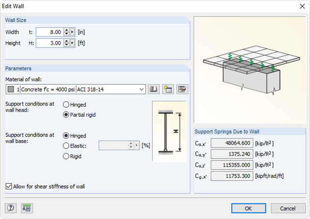
It is possible to specify nonlinearities of member end releases (yielding, tearing, slippage, and so on) and supports (including friction). There are special dialog boxes available for determining the spring stiffnesses of columns and walls based on the geometry specifications.

- Design of knee joints, T-joints, cross joints, and continuous column connections with I-shaped sections
- Import of geometry and load data from RFEM/RSTAB or manual specification of the connection (for example, for recalculation without an existing RFEM/RSTAB model)
- Flush top connections or connections with bolt row in extension
- Design of positive and negative frame joint moments
- Various inclinations of right and left horizontal beams as well as application to frames of duopitch and monopitch roofs
- Consideration of additional flanges in a horizontal beam, for example for tapered sections
- Symmetrical and asymmetrical T-joints or cross joints
- Two-sided connection with different cross-section depth on the right and left
- Automatic preliminary design of bolt layout and required stiffening
- Optional design mode with possibility to specify all bolt spacing, welds, and sheet thicknesses
- Screwability check with adjustable dimensions of used wrenches
- Connection classification by stiffness and calculation of the spring stiffness of connections considered in the internal forces determination
- Check up to 45 individual designs (components) of the connection
- Automatic determination of governing internal forces for each individual design
- Controllable connection graphics in rendering mode with specifications of material, sheet thickness, welds, bolt spacing, and all dimensions for construction
- Integrated and flexibly extensible settings of National Annexes according to EN 1993-1-8 standard
- Automatic conversion of internal forces from structural analysis into respective sections, also for eccentric member connections
- Automatic determination of initial stiffness Sj,ini of the connection
- Detailed plausibility check of all dimensions, including specifications of input limits (for example, for edge distances and hole spacing)
- Optional application of compression forces to a column through contact
- Possibility to update the cross-section depth of horizontal beams in case of tapered connections after connection geometry optimization in RF-/FRAME-JOINT Pro
Comprehensive and easy options in the individual input windows facilitate the representation of the structural system:
Nodal Supports
- The support type of each node is editable.
- It is possible to define a warp stiffening on each node. The resulting warp spring is determined automatically using the input parameters.
Elastic member foundation
- In the case of elastic member foundations, you can manually enter spring constants.
- Alternatively, you can use the various options to define the rotational and translational springs from a shear panel.
Member End Springs
- RF-/FE-LTB calculates the individual spring constants automatically. You can use the dialog boxes and detailed pictures to represent a translational spring by connecting component, a rotational spring by a connecting column, or a warping stiffener (available types: end plate, channel section, angle, connecting column, cantilevered portion).
Member Hinges
- If there are no member hinges defined in RFEM/RSTAB for the set of members, you can define them directly in the RF-/FE-LTB add-on module.
Load Data
- The nodal and member loads of the selected load cases and combinations are displayed in separate windows. There you can edit, delete, or add them individually.
Imperfections
- RF-/FE-LTB automatically applies the imperfections by scaling the lowest eigenvector.
.png?mw=640&hash=53c64389797699e939283ddbfc3d88485fcbfbf5)
- Full integration in RFEM/RSTAB, including import of all relevant loads
- General stress analysis with warping torsion according to elastic-elastic method
- Stability analysis of planar continuous members for buckling and lateral-torsional buckling
- Determination of critical load factor and thus of Mcr or Ncr (the factor can be used in RF-/LTB for the el/pl design)
- Lateral-torsional buckling analysis of any cross-section (also the SHAPE-THIN cross-sections)
- Design of members and sets of members with applied torsion (for example, crane girder)
- Optional determination of the limit load factor (critical load factor)
- Display of eigenmodes and torsional modes on the rendered cross-section
- Wide range of tools for determining shear panels and rotational restraints (such as corrugated sheets, purlins, bracings)
- Easy determination of discrete springs such as warp springs from end plates or rotational springs from columns
- Graphical selection of load application points on a cross-section (upper chord, centroid, lower chord, or any other point)
- Free arrangement of eccentric nodal and line supports on a cross-section
- Determination of value for inclination or precamber by means of eigenvalue analysis
- Special warping releases applicable for definition of warping conditions on transitions