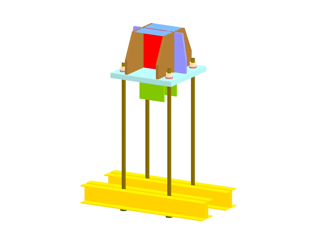
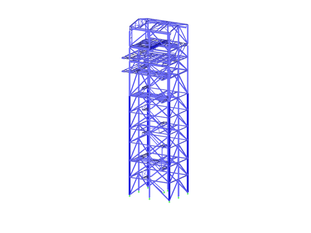
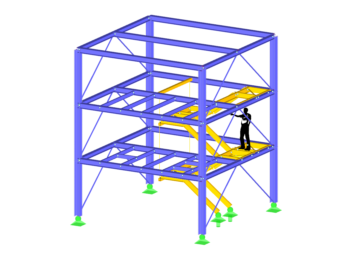
The model shows a high-rise industrial structure, constructed with precise steel connections. It presents detailed connection solutions, such as foundation connections, flag plates, shear force connections, frame joints, and end plate joints. Specific components, for example from Sikla, are integrated to optimally model industrial requirements. This model provides a practical display of innovative steel construction techniques and is ideal for visualizing complex connection concepts.
Model Used in
- UPD 003 | Update to Program Version x.25
- Quickly Determine Loads with the GEO-ZONE TOOL: Interactive Load Zone Maps with Google Technology
- WIN | 04/2024 – What's New in RFEM 6 and RSTAB 9?
- WIN | 05/2024 – What's New in RFEM 6 and RSTAB 9?
- WIN | 10/2024 – What's New in RFEM 6 and RSTAB 9?
- WIN | 11/2024 – What's New in RFEM 6 and RSTAB 9?
- WIN | 12/2024 – What's New in RFEM 6 and RSTAB 9?
- WIN | 01/2025 – What's New in RFEM 6 and RSTAB 9?
Industrial Building Tower with Steel Joints
| Number of Nodes | 414 |
| Number of Lines | 611 |
| Number of Members | 603 |
| Number of Surfaces | 1 |
| Number of Load Cases | 14 |
| Number of Load Combinations | 134 |
| Number of Result Combinations | 7 |
| Total Weight | 131,918 t |
| Dimensions (Metric) | 11.877 x 15.853 x 17.077 m |
| Dimensions (Imperial) | 38.97 x 52.01 x 56.03 feet |
| Program Version | 5.12.02 |
You can download this structural model to use it for training purposes or for your projects. However, we do not assume any guarantee or liability for the accuracy or completeness of the model.
Related Models