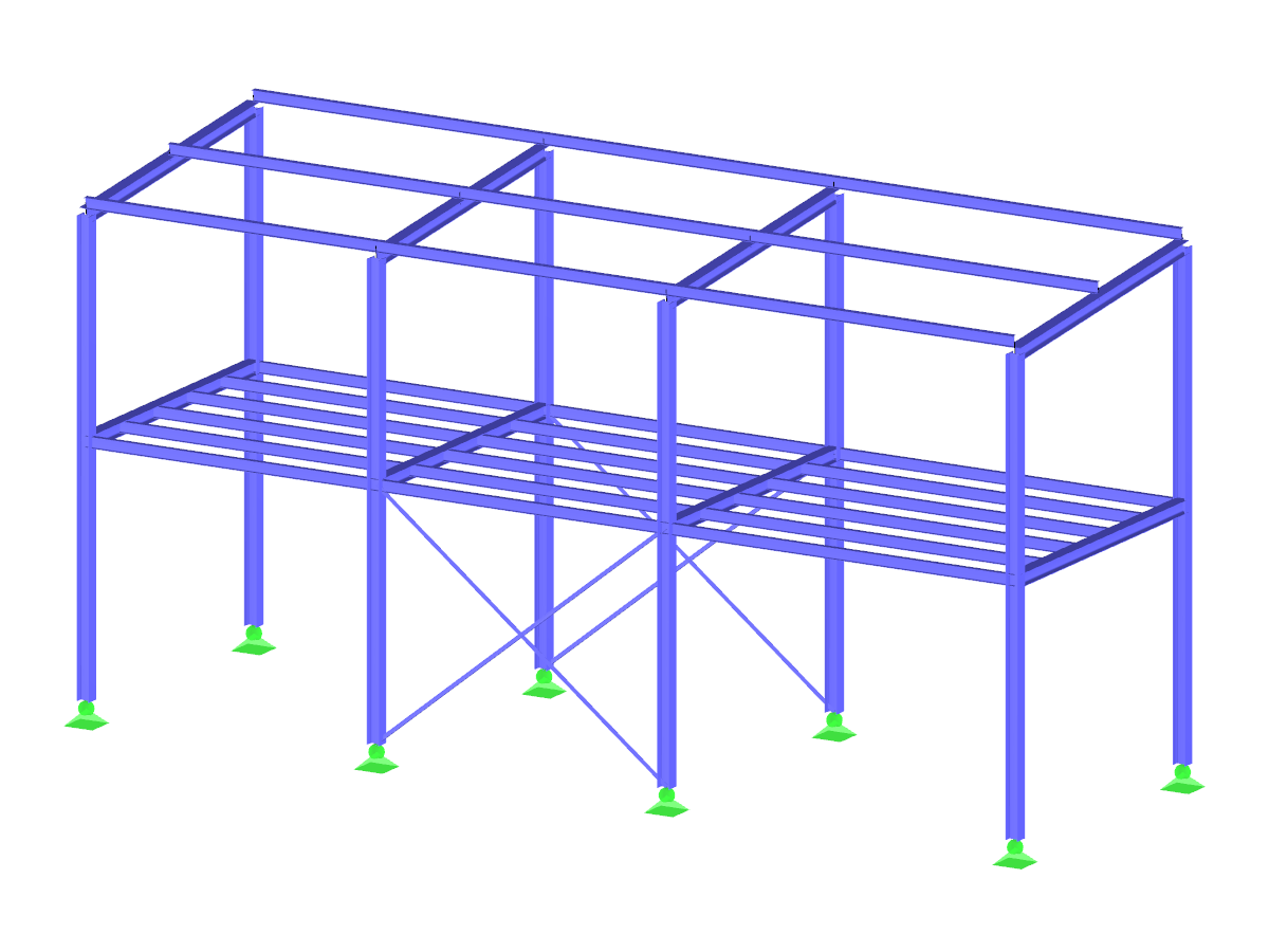
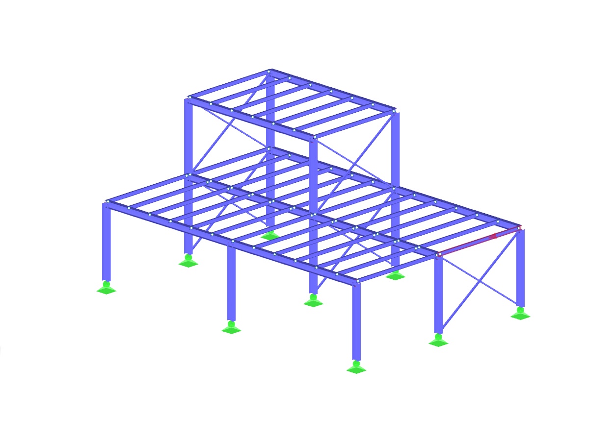
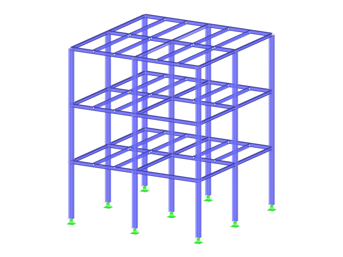
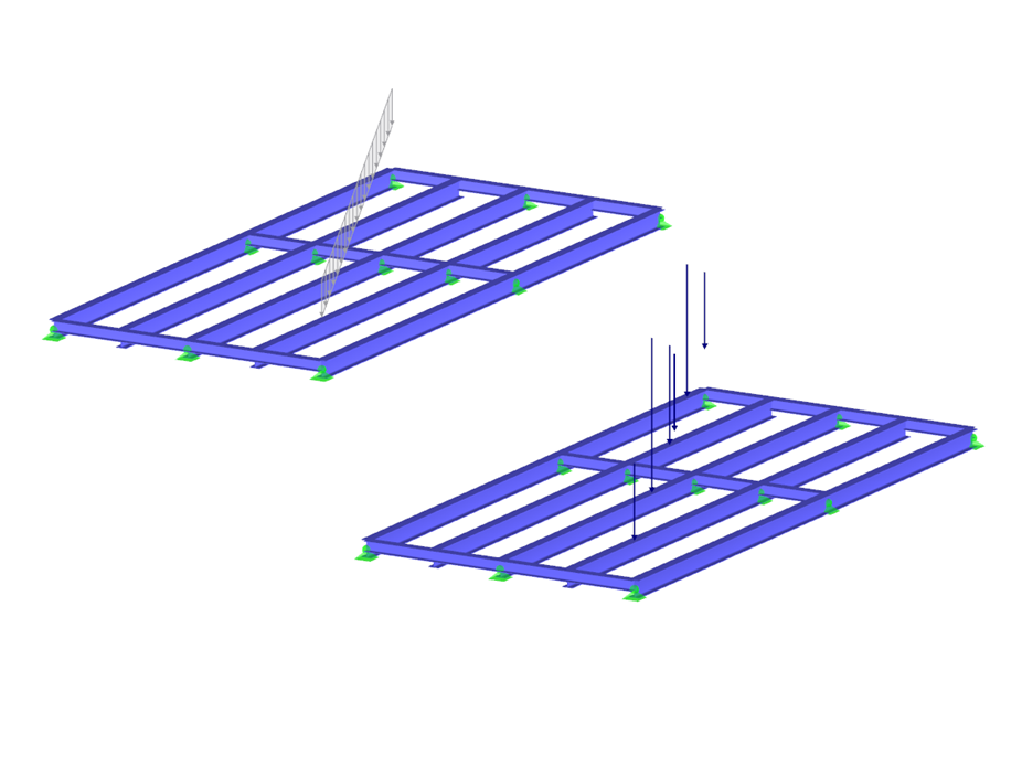
Steel Frame with Pipe Load
Model to Download
Description
Not all structural elements of a real building are included in a structural model.
This model is an example of the generation of member loads from free line loads.
The pipeline should be positioned on a steel frame in this case. The load of the beam would be transferred as concentrated loads on the beam below. To avoid manually splitting the according portions of the load, click ‘Tools’, point to ‘Generate Loads’, and then select the load generator ‘From Free Line Load’.
Model Used in
Keywords
Load generator Line load Member load
Links
Write Comment...
Write Comment...
Disclaimer

New
Not all structural elements of a real building are included in a structural model. As an example, we can look at a pipe that runs along a steel girder frame.
SHAPE-THIN determines the effective cross-sections according to EN 1993-1-3 and EN 1993-1-5 for cold-formed sections. You can optionally check the geometric conditions for the applicability of the standard specified in EN 1993‑1‑3, Section 5.2.
The effects of local plate buckling are considered according to the method of reduced widths and the possible buckling of stiffeners (instability) is considered for stiffened sections according to EN 1993-1-3, Section 5.5.
As an option, you can perform an iterative calculation to optimize the effective cross-section.
You can display the effective cross-sections graphically.
Read more about designing cold-formed sections with SHAPE-THIN and RF-/STEEL Cold-Formed Sections in this technical article: Design of a Thin-Walled, Cold-Formed C-Section According to EN 1993-1-3.
- How can I consider continuity effects in load generators?
- Why do I get duplicated values for the load generation "Conversion of Area Load to Member Loads"?
- Does the load generation also work for curved members?
- I use the load generator to apply a load on two members that connected at an angle to each other. Why are the load values on the member ends not the same?
- How is it possible to consider the real cross-section geometry of member elements in RWIND Simulation?
- I am trying to manually check the deformations from the CRANEWAY add-on module. However, I obtain great deviations. How to explain the differences?
- What should be considered when using a failure of columns under tension in the RF‑/DYNAM Pro – Equivalent Loads add-on module?
- Why is there no stability analysis displayed in the results despite the activation of the stability analysis in RF‑/STEEL EC3?
- How can I model and design a crane runway girder with Dlubal Software?
- Is it possible to set user-defined values when viewing solid stress results?