Check out these tips to help you get started with the RFEM program.
Effective depth
Video
First Steps with RFEM
Description
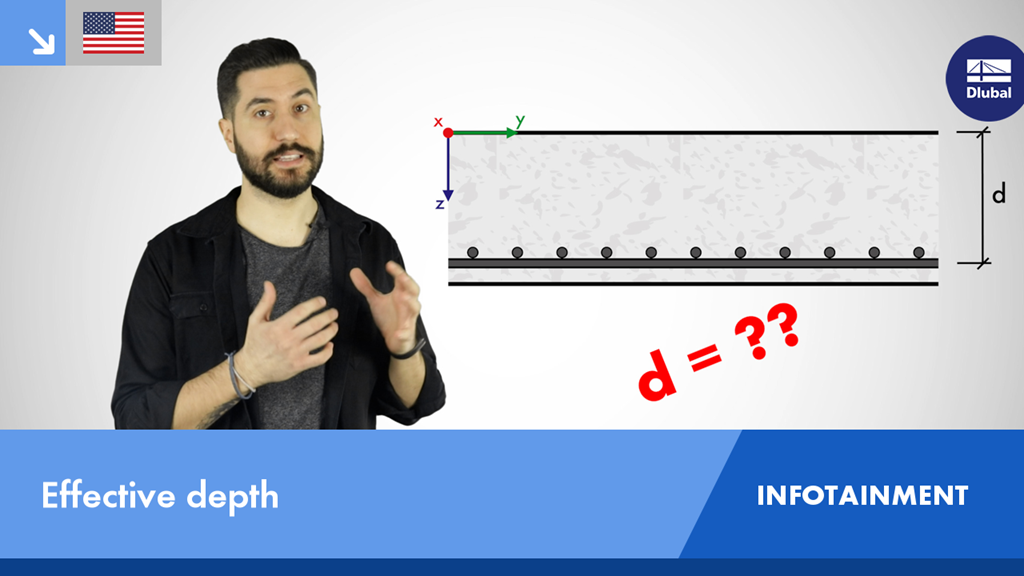
What is the effective depth? In short, this is the distance between the component edge of the compression side and the centroid of the tension reinforcement.
It is directly related to the bending design of a component because it defines the inner lever arm and therefore also the acting tensile and compressive forces.
In this video, we will show you how to find out the effective depth of a component and then where to find it in the RF-CONCRETE Surfaces add-on module.
Have fun!
Keywords
Dlubal Infotainment Structural analysis - basics Structural analysis Civil engineering studies Structural Design Concrete structure Concrete Reinforced concrete RF-CONCRETE Surfaces E-learning Entertainment Construction industry Civil engineering Civil engineer Studies Structural engineering Structural engineer
Write Comment...
Write Comment...
Contact Us
Do you have any questions about our products or which are best suited for your design projects? Contact us via phone, email, or chat or find suggested solutions and useful tips on our FAQ page available 24/7.

New
Modal Analysis in RFEM 6 Using a Practical Example
Modal analysis is the starting point for the dynamic analysis of structural systems. This article shows you a summary of how to perform a modal analysis in RFEM 6.

Features of RF-CONCRETE Surfaces
- Free definition of two or three reinforcement layers in the ultimate limit state
- Vectorial representation of the main stress directions of internal forces allowing optimal orientation adjustment of the third reinforcement layer to the actions
- Design alternatives to avoid compression or shear reinforcement
- Design of surfaces as deep beams (theory of membranes)
- Option to define basic reinforcements for top and bottom reinforcement layer
- Definition of designed reinforcement for serviceability limit state design
- Results output in grid points of any selected grid
- Optional extension of the module with nonlinear deformation analysis. The calculation is performed in RF‑CONCRETE Deflect by reducing the stiffness according to the standard, or in RF‑CONCRETE NL by the general nonlinear calculation determining the stiffness reduction in an iterative process.
- Design with design moments at column edges
- Itemization of reasons for failed design
- Design details of all design locations for better traceability of reinforcement determination
- Export of isolines for the longitudinal reinforcement in a DXF file for further use in CAD programs as a basis for reinforcement drawings
- It takes a long time to save my structure. What can be the reason?
-
The limit stress is activated, but my stress ratio is “non-designable” in the Stress-Strain Analysis add-on. What could be the reason?
- In RFEM 6, is it possible to display a graphic with the distribution of the required reinforcement in the DIN A0 format?
- How do I define a member as a cantilever and not as supported at both ends for serviceability or deflection design?
- In RFEM 6, is it possible to display a graphic with the distribution of the required reinforcement in the DIN A0 format?