Answer:
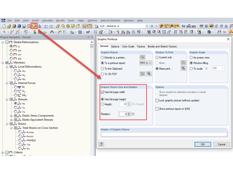
You can adjust the height and width of a graphic in the "Graphic Printout" dialog box → "General Settings" tab → "Graphic Image - Size and Rotation".
Sign up for the Dlubal Extranet to get most of the software and have exclusive access to your personal data.
Sign up for the Dlubal Extranet to get most of the software and have exclusive access to your personal data.
Sign up for the Dlubal Extranet to get most of the software and have exclusive access to your personal data.
How can I adjust the height and width of a graphic in RFEM 5 / RSTAB 8?
You can adjust the height and width of a graphic in the "Graphic Printout" dialog box → "General Settings" tab → "Graphic Image - Size and Rotation".
Mr. Faulstich is responsible for the quality assurance of the RFEM program and provides customer support.