Special structures such as nuclear power plants, offshore structures, and large dams are not considered in these regulations [1]. The stated aim of these regulations is to ensure that, in case of an earthquake,
- human lives are protected,
- damage is limited, and
- structures important for civil protection remain operational.
An earthquake represents an action on the structure induced by the soil. The action therefore corresponds to a group of imposed deformations or accelerations. To combine this action with other actions (imposed load, snow, etc.) in defined design situations according to the combination standard DIN EN 1990, the action resulting from seismic activity is classified as seismic action.
Functional Requirements
Structures in earthquake zones must meet certain requirements with regard to stability and damage limitation.
Concerning the structural stability, it has to be ensured that the structural system withstands the defined design earthquake without local or global collapse, thus retaining its structural integrity and a residual load-bearing capacity after seismic events. In this case, the reference design earthquake has to be determined with a reference return period of TNCR = 475 years [2]. This corresponds to a probability of occurrence or exceedance of 10% within 50 years.
In addition, with regard to damage limitation, it is necessary to ensure that the structure is designed and constructed to withstand a seismic action
Target reliabilities for the no-collapse requirement and for the damage limitation requirement are implemented by classifying structures into different importance classes. An importance factor γI is assigned to each importance class, serving as a modification value of the reference seismic action to determine the design earthquake [1]. The importance class II corresponds to the TNCR of the reference earthquake.
| Importance Class | Building | Importance Factor γI |
|---|---|---|
| I | Buildings of minor importance for public safety (for example,agricultural buildings, etc.) | 0.8 |
| II | Ordinary buildings not belonging to the other categories (smaller residential and office buildings, workshops, etc.) | 1.0 |
| III | Buildings of which the seismic resistance is important in view of the consequences associated with a collapse (huge residential buildings, schools, assembly halls, malls, etc.) | 1.2 |
| IV | Buildings of which the integrity during earthquakes is of vitalimportance for civil protection (hospitals, important civil protection facilities, fire department, security staff, etc.) | 1.4 |
Compliance Criteria - Ultimate Limit States
To satisfy the defined functional requirements of a building under seismic action, the ultimate and serviceability limit states have to be checked.
Ultimate limit states describe possible collapse scenarios or other structural failures of the considered building [1]. To ensure compliance, the ductility with regard to the requirements and the structural stability of the entire building, including all foundation components and the soil, must be ensured.
However, the serviceability limit states focus on damage that limits the serviceability [1]. To ensure sufficient reliability against damage, the relevant deformation limits must be ensured. In addition, important buildings have to be designed as correspondingly rigid to protect the population with sufficient resistance to maintain the most important services.
Ductility
In general, an earthquake applies energy to a building and induces vibrations [2]. The corresponding building oscillation as well as the seismic load depend on the building properties. With regard to earthquakes, buildings can be designed in such a way that they can carry relatively high-acting forces with little elastic deformation or smaller-acting forces with larger plastic deformations. The second solution leads to significantly higher energy dissipation, which requires a physically nonlinear calculation of the structural system. In practice, the behavior factor q depending on a certain ductility classification is used to get the equilibrium between loading and energy dissipation [1]. The higher the ductility class, the smaller the equivalent seismic loading. However, the higher the ductility class, the higher the structural design requirements to ensure ductility.
| Ductility Class of the Structure | Behavior Factors q | |
|---|---|---|
| Low-Dissipative Structural Behavior | DCL (low) | ≤ 1.5 |
| Dissipative Structural Behavior | DCM (mean) | Concrete components according to DIN EN 1998-1, Chapter 5 Steel structures according to DIN EN 1998-1, Chapter 6 Composite structures made of steel and concrete according to DIN EN 1998-1, Chapter 7 Timber structures according to DIN EN 1998-1, Chapter 8 Masonry structures according to DIN EN 1998-1, Chapter 9 |
| DCH (high) |
Seismic action
The earthquake standard describes ground motion occurring at a certain point on the Earth's surface with an elastic ground acceleration response spectrum (also known as an elastic response spectrum). The elastic response spectrum is identical with regard to the set requirements for structural stability and damage limitation.
Since the seismic action is reduced by means of a nonlinear reaction for most structures, a nonlinear calculation is necessary for determination [1]. To simplify, it is possible to determine the ductile behavior of buildings with a linear calculation on the basis of an elastic response spectrum modified with the behavior factor q. The response spectrum modified with q is called the design spectrum [1]. The behavior factor q is related to a 5% viscous damping of the structure.
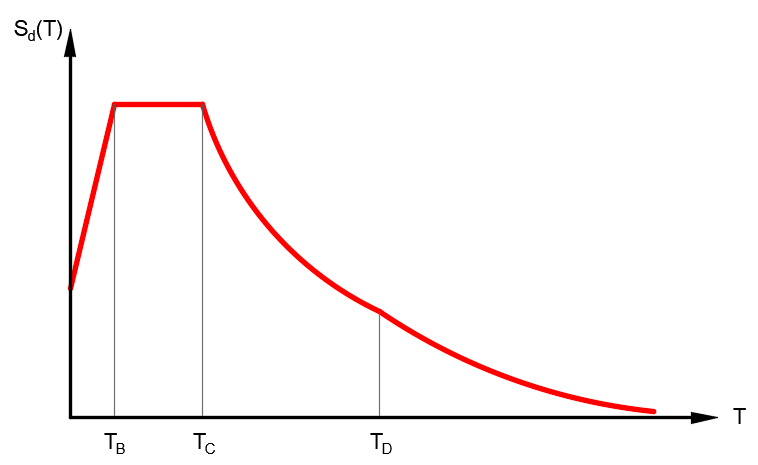
| Area | Function of the Design Spectrum Sd(T) |
|---|---|
| 0 ≤ T ≤ TB | agR ⋅ γI ⋅ S ⋅ [1 + T/TB ⋅ (2.5/q - 1)] |
| TB ≤ T ≤ TC | agR ⋅ γI ⋅ S ⋅ 2.5/q |
| TC ≤ T ≤ TD | agR ⋅ γI ⋅ S ⋅ 2.5/q ⋅ TC/T |
| TD ≤ T | agR ⋅ γI ⋅ S ⋅ 2.5/q ⋅ (TC ⋅ TD)/T2 |
Sd(T) = ordinate of the design spectrum
T = vibration period of a linear single-mass oscillation
γI = importance factor
q = behavior factor
agR = reference peak ground acceleration
TB, TC, TD = Control periods of the response spectrum
S = soil factor
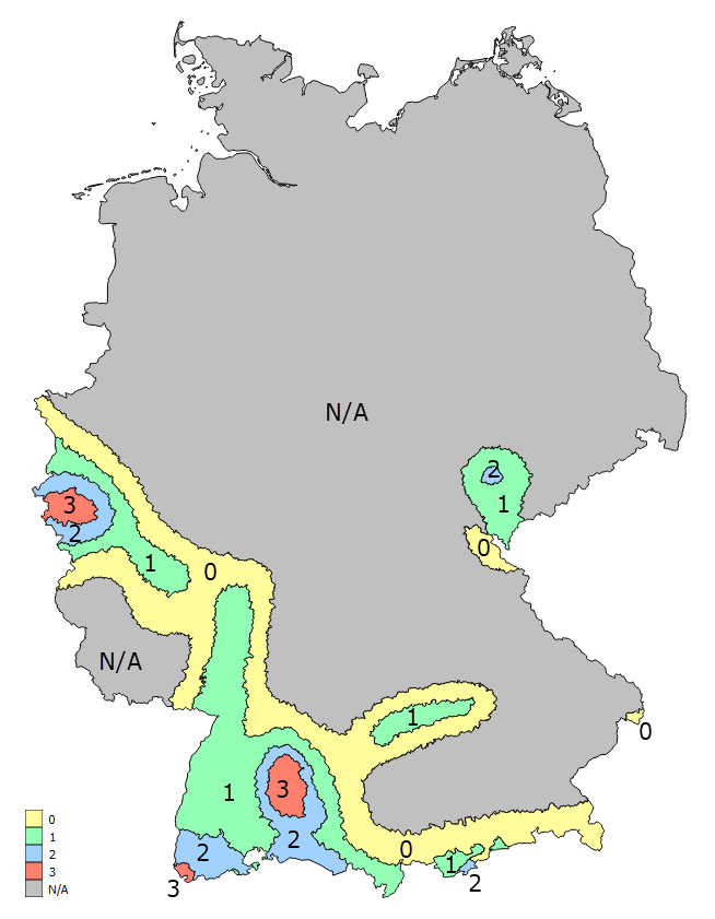
The reference peak ground acceleration agR is a site-specific value. The value results from a seismic risk analysis of the Federal Republic of Germany. Depending on the local hazard, the country is grouped into corresponding seismic zones, 0 to 3. Within each zone, the hazard is assumed to be constant and classified with a corresponding value of the reference peak ground acceleration agR [1].
| Seismic zone | Value of the reference peak ground acceleration agR in m/s2 |
|---|---|
| 0 | not specified |
| 1 | 0.4 |
| 2 | 0.6 |
| 3 | 0.8 |
| N/A | not specified |
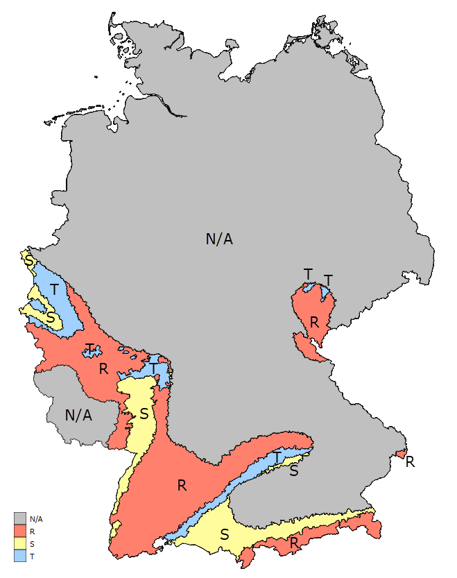
The control periods TB, TC, and TD, and the soil factor S defined for the design spectrum are also site-specific values and are based on a combination of ground foundation class and subsoil class [1] present at the place of construction.
| Soil Conditions | S | TB in s | TC in s | TD in s |
|---|---|---|---|---|
| A-R | 1.00 | 0.01 | 0.20 | 2.0 |
| B-R | 1.25 | 0.01 | 0.25 | 2.0 |
| C-R | 1.50 | 0.01 | 0.30 | 2.0 |
| B-T | 1.00 | 0.01 | 0.30 | 2.0 |
| C-T | 1.25 | 0.01 | 0.40 | 2.0 |
| C-S | 0.75 | 0.01 | 0.50 | 2.0 |
The ground, which is dependent on the shear wave velocities, is divided into classes A, B, and C [1]:
- Ground Type A
- Non-weathered (fresh) solid rocks with high strength
- Dominant shear wave velocities are higher than about 800 m/s
- Ground Type B
- Moderately weathered solid rocks or solid rocks with low strength
- Coarse-grained (incohesive) or mixed-grain unconsolidated soil with high friction properties in a dense or solid consistency (for example, glacial loose rock)
- Dominant shear wave velocities range between about 350 m/s and 800 m/s
- Ground Type C
- Heavily or completely weathered solid rocks
- Coarse-grained (incohesive) or mixed-grain unconsolidated soil in medium-dense soil or in at least a stiff consistency
- Fine-grained (cohesive) soil in at least a stiff consistency
- Dominant surface wave measurements range between about 150 m/s and 350 m/s
The changing subsoil between rock and sediment is divided into subsoil classes R, T, and S [1]:
- Subsoil class R
- Areas predominantly characterized by rocks
- Subsoil class T
- Transition zones between subsoil class R and subsoil class S, as well as areas of relatively shallow sedimentary basins
- Subsoil class S
- Areas with deep basin structures with thick sedimentary fill
Determining the Local Reference Peak Value of Ground Acceleration and the Subsoil Class
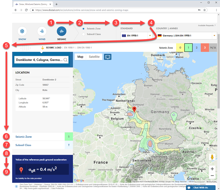
The Geo-Zone Tool, located on the Snow, Wind, and Seismic Zoning Maps Dlubal webpage, includes the standard requirements as well as the digital solutions of the Internet. Depending on the selected load type (snow, wind, seismic action) and the country-specific standard, this tool determines the corresponding data based on Google Maps. Enter the location, geographic coordinates, or local conditions in the search function to get the relevant data. The tool then determines the characteristic load or acceleration at this location by means of the exact height above sea level and the zone data entered. If it is impossible to define the location by means of a specific address, you can zoom into the map and select the correct location. When selecting the correct location on the map, the calculation will be adapted to the new altitude and will display the updated loads.
The online service is available on the Dlubal website at Solutions → Online Services.
By defining the parameters...
1. load type = seismic
2. standard = EN 1998-1
3. map level = seismic zone or subsoil class
4. annex = Germany | DIN EN 1998-1
5. address = Domkloster 4, Cologne
...it results in the following for the selected location:
6. seismic zone
7. subsoil class
8. additional information, if applicable
9. value of the reference peak ground acceleration agR