The structural analysis software RFEM 6 is the basis of a modular software system. The main program RFEM 6 is used to define structures, materials, and loads of planar and spatial structural systems consisting of plates, walls, shells, and members. The program also allows you to create combined structures as well as to model solid and contact elements.
RSTAB 9 is a powerful analysis and design software for 3D beam, frame, or truss structure calculations, reflecting the current state of the art and helping structural engineers meet requirements in modern civil engineering.
Do you often spend too long calculating cross-sections? Dlubal Software and the RSECTION stand-alone program facilitate your work by determining section properties of various cross-sections and performing a subsequent stress analysis.
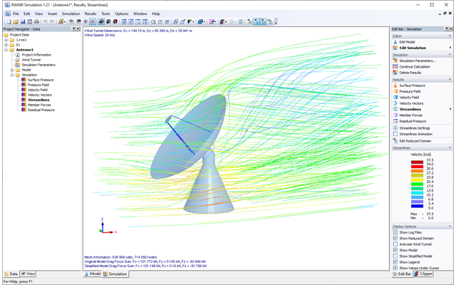
Do you always know where the wind is blowing from? From the direction of innovation, of course! With RWIND 2, you have a program at your side that uses a digital wind tunnel for the numerical simulation of wind flows. The program simulates these flows around any building geometry and determines the wind loads on the surfaces.
Are you looking for an overview of snow load zones, wind zones, and seismic zones? Then you are in the right place. Use the Geo-Zone Tool to determine quickly and efficiently snow loads, wind speeds, and seismic data according to ASCE 7‑16 and other international standards.
Would you like to try out the capabilities of the Dlubal Software programs? You have the opportunity to do so! The free 90-day full version allows you to thoroughly test all our programs.
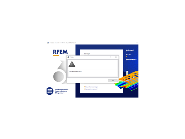
If this error message appears, RFEM/RSTAB cannot connect to the server managing the cloud calculations.
Please ask your IT department to check the communication with our server. It is necessary to enable the following access in the firewall policies as well as in the network:
If the connection still does not work after this procedure, your IT department needs to check whether the SSL certificate has been exchanged, based on your internal guidelines (for example, using a proxy). They should be able to check this with software (for example, OpenSSL) in the command line:
If you see this error message, you cannot connect to our license server to verify your license.
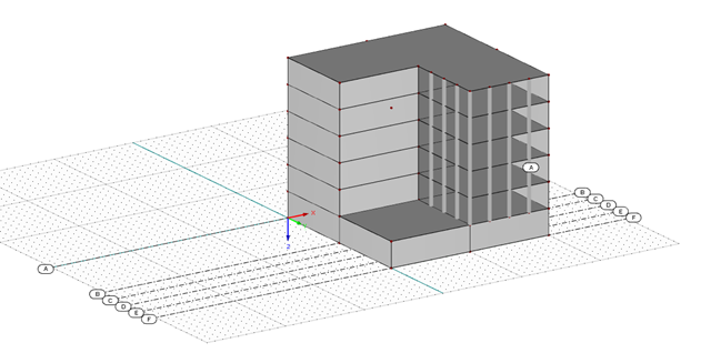
Instead of guidelines, you can use line grids that can be created in 3D.
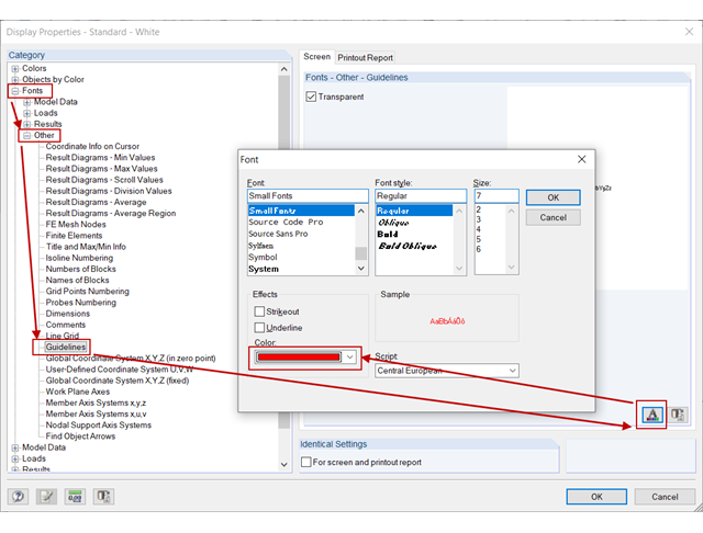
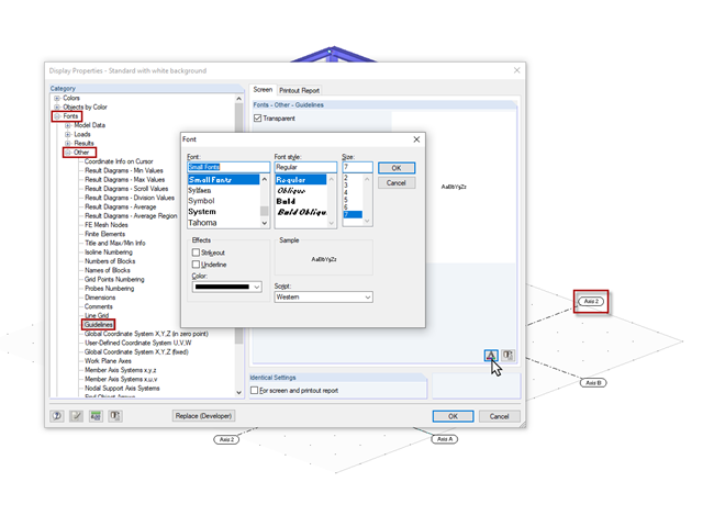
The font color of the guideline numbering can be changed in Display Properties:
Right-click the workspace → Display Properties → Fonts → Other → Guidelines → "Font" button → Change Color; see the image.
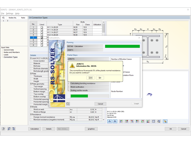
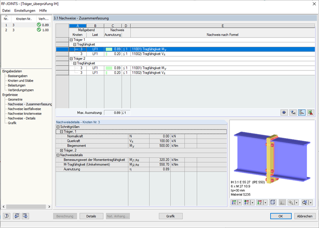
Originally, the typified moment-resistant connections of the DSTV guidelines were not designed to be subjected to normal force. However, a load of up to 5% of the plastic normal force resistance of the connected beam may be neglected according to the instructions given in the guideline. If the beam contains a higher normal force, a warning message is also given in RF‑/JOINTS Steel - DSTV.
With the additional volume of the 2018 guideline, additional moment-resistant connections of the IM designation were added. In the beam-to-beam connection type, they are also designed to resist the normal forces. If you design such a connection, the normal force resistance design including the MN interaction appears instead of the warning message.
For beam-column connections, the normal force resistance of column components is not included in the table values according to the DSTV guideline. Therefore, the connection must be designed separately again. Consequently, the warning message appears anyway. As an alternative, you can use RF‑/JOINTS Steel - Rigid.
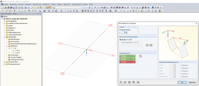
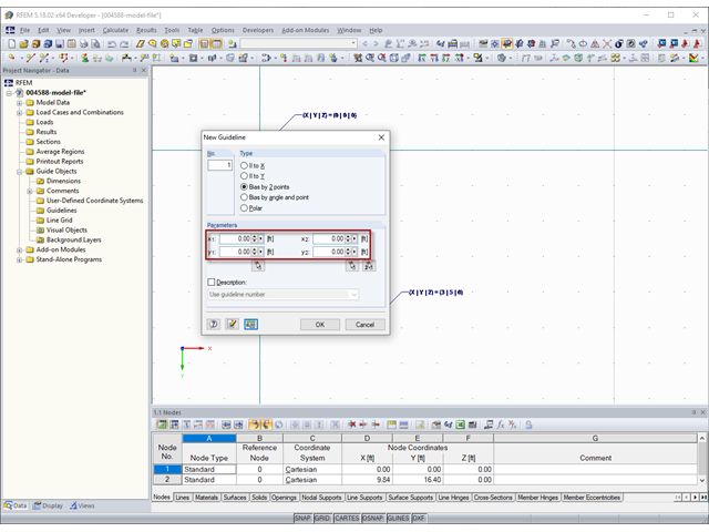
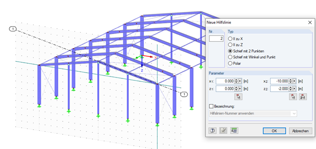
The coordinates of guidelines (Image 01) to be specified in the "New Guideline" dialog box under "Parameters" refer to the zero point of the work plane.
You can set the zero point of the work plane in the "Work Plane and Grid/Snap" dialog box (Image 02) using the menu Tools→ Select Work Plane → Set Origin or the corresponding button in the toolbar.
In the video, the zero point of the work plane is set to the coordinates X = 3 m, Y = 5 m, and Z = 0 m. Then, a guideline is created parallel to X (|| to X) with the coordinate y1 = 0 m. Thus, the guideline is in the global coordinate system at Y = 5 m.
You can find this setting in Display Properties under the "Font", "Other", and "Guidelines" categories.
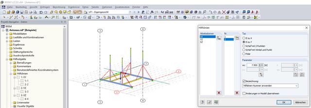
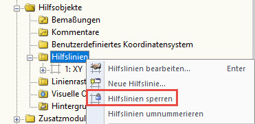
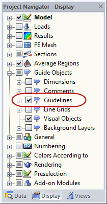
You can control the display of guidelines in Project Navigator - Display (see Image 01). Furthermore, you can define whether to display only the model, or some or all existing guidelines in the overall view of the model. If the guidelines protrude far beyond the model, the entire view can be limited to the model (see Image 02).