The structural analysis software RFEM 6 is the basis of a modular software system. The main program RFEM 6 is used to define structures, materials, and loads of planar and spatial structural systems consisting of plates, walls, shells, and members. The program also allows you to create combined structures as well as to model solid and contact elements.
RSTAB 9 is a powerful analysis and design software for 3D beam, frame, or truss structure calculations, reflecting the current state of the art and helping structural engineers meet requirements in modern civil engineering.
Do you often spend too long calculating cross-sections? Dlubal Software and the RSECTION stand-alone program facilitate your work by determining section properties of various cross-sections and performing a subsequent stress analysis.
Do you always know where the wind is blowing from? From the direction of innovation, of course! With RWIND 2, you have a program at your side that uses a digital wind tunnel for the numerical simulation of wind flows. The program simulates these flows around any building geometry and determines the wind loads on the surfaces.
Are you looking for an overview of snow load zones, wind zones, and seismic zones? Then you are in the right place. Use the Geo-Zone Tool to determine quickly and efficiently snow loads, wind speeds, and seismic data according to ASCE 7‑16 and other international standards.
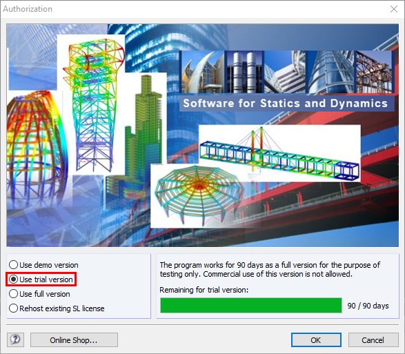
Would you like to try out the capabilities of the Dlubal Software programs? You have the opportunity to do so! The free 90-day full version allows you to thoroughly test all our programs.
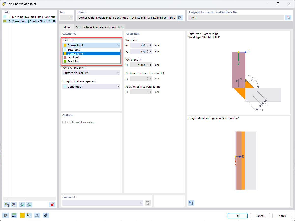
Where the geometries become complicated, it is difficult to use analytical methods for the design. The weld elements in RFEM 6 are particularly helpful for such applications.
RFEM 6 allows for design checks for different types of welds.
In the Joint type list, you can select how the surfaces to be connected are related to each other.
Then, select a weld type.
Finally, it is necessary to define the weld parameters.
The welds do not affect the stiffness of the model. You use the stresses from the surface elements and evaluate them according to the regulations.
The CRANEWAY program can only design the main girders, not the bridge crane itself. The endcarriages of the bridge crane are also not designed.
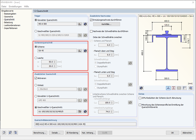
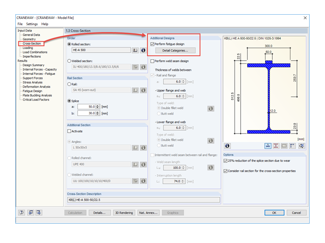
For an overhead crane, you can define the parameters of the rail cross-section as well as an additional cross-section in Window 1.3 of CRANEWAY.
For a splice, you can define the width a and the height b. Beam cross-sections made of rolled or welded sections can be combined with a rail or a splice. If the rail cross-section is too large or the girder cross-section is too small, you can only continue the entry with a plausible crane girder section.
Angled and channel cross-sections are possible as additional cross-sections. They can be selected as beam cross-sections in the [Library] or defined using the button.
On our website, you can find an interesting webinar about "Design of Craneway Girders According to Eurocode 3".
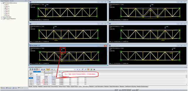
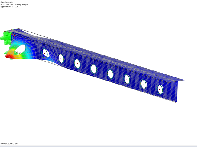
Based only on the surface results or surface stresses, it is not possible to make a statement about the buckling behavior of the box girder. The stability behavior can be analyzed using the RF‑STABILITY add-on module. It determines the buckling shapes and critical load factors that allow a statement about the buckling behavior.
However, the buckling design has not yet been provided. For this purpose, the buckling shape would have to be transferred to the model, so it can be calculated according to the second-order analysis on the imperfect structural system. A stress analysis with the RF‑STEEL add-on module could then be used to carry out a buckling design.
The RF‑IMP add-on module facilitates the transfer of the buckling shape. Using this module, you can generate the equivalent geometry based on the stability mode so that you can perform a buckling design with a second-order stress analysis on the predeformed structure using RF‑STEEL.
The procedure in RFEM could look like this:
As an alternative, you can use the PLATE-BUCKLING module to analyze the buckling behavior.
There are some very interesting technical articles on this topic on our website.
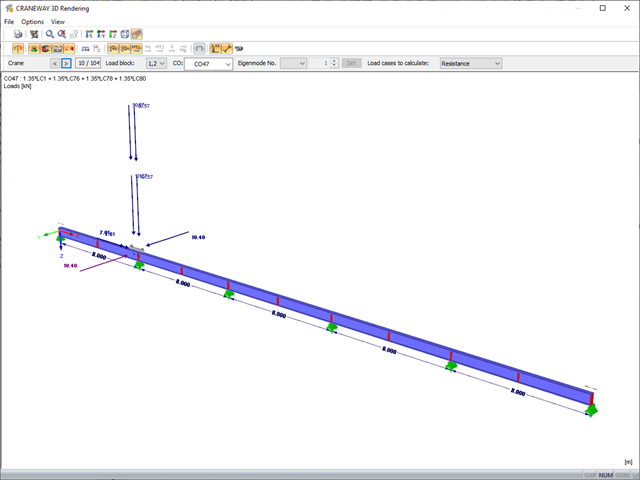
For modeling and design of crane runway girders, we provide the stand-alone program CRANEWAY.
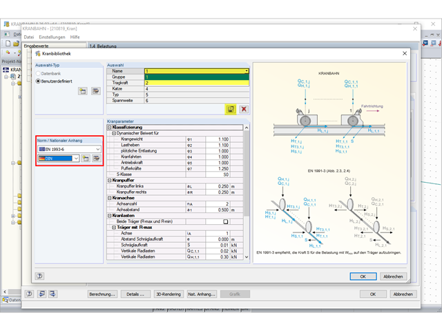
It is possible to import cranes from the crane library or a user-defined crane database.
However, the database does not contain any templates for design according to EN 1993‑6, so you can only create your own templates for your crane database.
If you select DIN 4132, you will find templates for the manufacturers DEMAG and KÜHNEZUG.
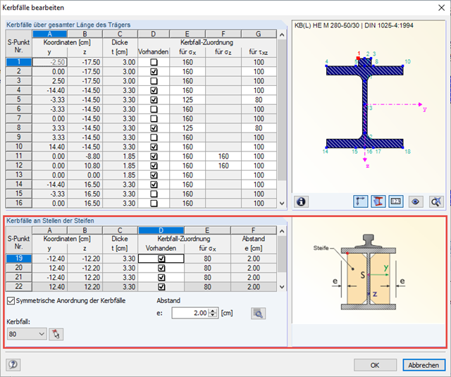
The fatigue design is activated in Window 1.3 "Cross-Section" under "Additional Designs"; see the image.
When you activate the fatigue design, the "Detail Categories" button becomes active. Here you can enter specifications for all relevant stress points in the "Edit Detail Categories" dialog box.
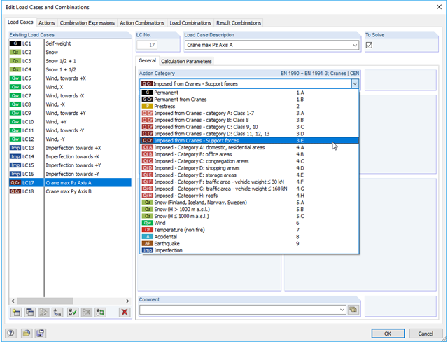
The standard EN 1991‑3, Table 2.2., specifies load groups 1 to 10. These are equal to the denotation of the classes in our software.
The integration in Categories A to E is a specific classification by Dlubal Software.
The article in our Knowledge Base (see Links below) points out that the combinations (Classes A to D) should be used for the preliminary design of crane girders. For the supporting structure (brackets, supports, trusses), these combinatorics should not be used.
In your model, the support loads from the crane girder design are only considered in Category E.