13 Results
View results:
Sort by:

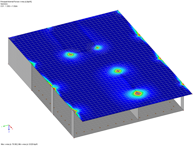
The optimal scenario in which punching shear design according to ACI 318-19 [1] or CSA A23.3:19 [2] should be utilized is when a slab is experiencing a high concentration of loading or reaction forces occurring at one single node. In RFEM 6, the node in which punching shear is an issue is referred to as a punching shear node. The causes of these high concentration of forces can be introduced by a column, concentrated force, or nodal support. Connecting walls can also cause these concentrated loads at wall ends, corners, and ends of line loads and supports.

The punching shear design, in line with EN 1992-1-1, should be performed for slabs with a concentrated load or reaction. The node where the design of punching shear resistance is performed (that is, where there is a punching problem) is called a node of punching shear. The concentrated load at these nodes can be introduced by columns, concentrated force, or nodal supports. The end of the linear load introduction on slabs is also regarded as a concentrated load and therefore, the shear resistance at wall ends, wall corners, and ends or corners of line loads and line supports should be controlled as well.
One of the advantages of entering the structure in RFEM is the complete freedom when selecting the geometry. You can easily select a structure where re‑entrant rolling corners are given as shown in the image.
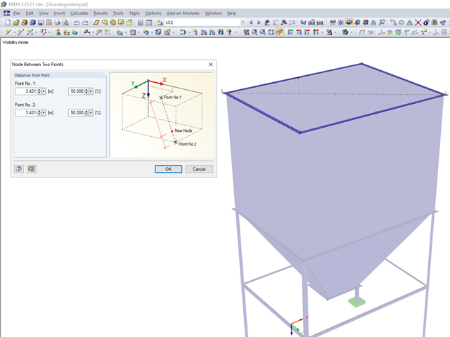
Until now, if you wanted to determine the centroid of a rectangle, it was necessary to define a line from one corner point to the diagonally opposite point. You obtained the centroid by dividing this line. In RFEM 5 and RSTAB 8, you now have the possibility to create a node between two points. Thus, it is sufficient to select the corner points; then you can determine the distance in absolute or relative values.
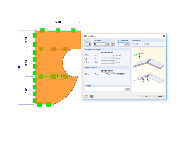
In RF-PUNCH Pro, you can perform the punching shear design on wall corners and wall ends. The basis for the design is the punching load, which is automatically determined from the RFEM internal forces in the connected surface. Since the surface internal forces from the RFEM calculation may be subject to the influence of singularity locations, this can also have a negative influence on the determined punching load at the wall corner or end. This article describes possible optimization options that you can use to minimize this unfavorable influence.

RF-PUNCH Pro performs punching shear design on concentrated load application locations (column connection, nodal support, and nodal load) as well as on wall ends and wall corners.
The RF-PUNCH Pro add-on module allows you to perform punching shear designs according to EN 1992‑1‑1 [1]. In addition to the design checks of single columns, wall ends and wall corners can be analyzed in RF‑PUNCH Pro. At this point, I would also like to reference a previous article about RF‑PUNCH Pro, which explains how to determine punching load on wall ends and wall corners.
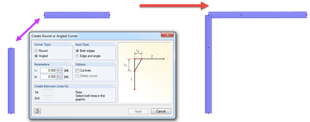
If there are two member ends to be connected, you can do this easily using the "Create Round or Angled Corner" function.
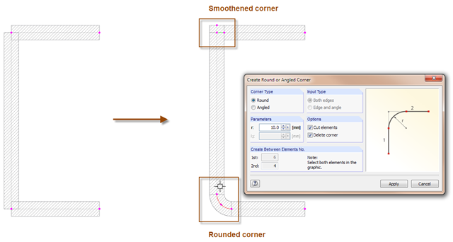
With the SHAPE-THIN cross-section program, you can model the corner areas of cross-sections in detail: The "Smooth Corner" function fills the corner with an element and automatically connects it with a null element. For this, simply click the corner. Use the "Create Round or Angled Corner" function to round or angle the corner. To do this, specify the fillet radius and click both elements.

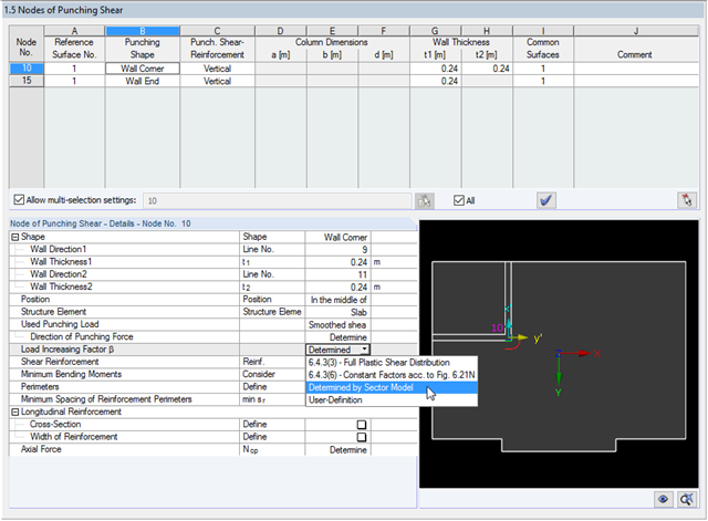
For structural components consisting of slabs, it is necessary to perform shear design on the locations with concentrated load introduction, applying the punching shear design rules according to Sect. 6.4 of EN 1992‑1‑1 [1]. The concentrated load introduction is present on the individual locations, for example by columns, concentrated load, or nodal supports. In addition, the end of linear load introduction on slabs is also regarded as concentrated load introduction. For example, this includes wall ends, wall corners, and ends or corners of line loads and line supports. You can perform the punching shear design for floor slabs or foundations, considering the existing available plate topology about the designed node of punching shear. The punching shear design according to EN 1992‑1‑1 checks that the acting shear force vEd does not exceed the resistance vRd.
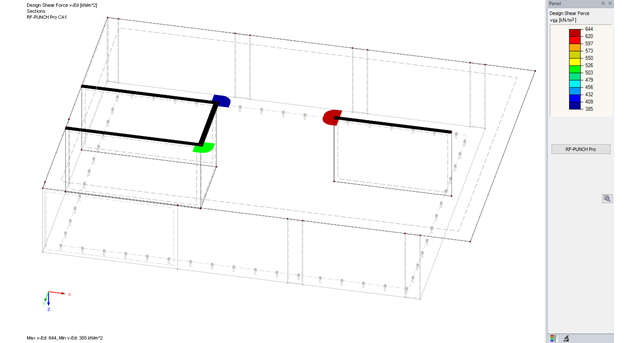
The RF-PUNCH Pro add-on module allows you to perform punching shear design of slabs and foundation plates (floor slabs) on wall ends and wall corners.

The form-finding process in RF-FORM-FINDING displaces the corner nodes of FE elements of a membrane surface in space until the defined surface stress is in equilibrium with the boundary conditions. This displacement is independent of the element geometry. In the case of elements with four corner nodes, the free displacement may cause spatial drilling in the element plane and thus exceed the validity limits of the calculation; therefore, triangular elements are generally recommended for form‑finding systems. Triangular elements remain independent of the corner node displacement and stay within the calculation limitations.
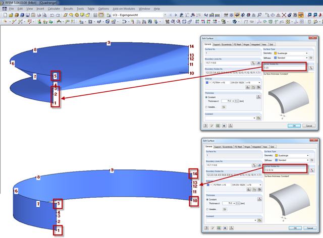
When creating a quadrangular surface, RFEM can automatically detect the four corner nodes. For more complex structures, it can happen that the optimal corner nodes are not found. Manually entering the four corner nodes can lead to a better result, in this case.