


Determining Punching Load on Wall Corners and Wall Ends
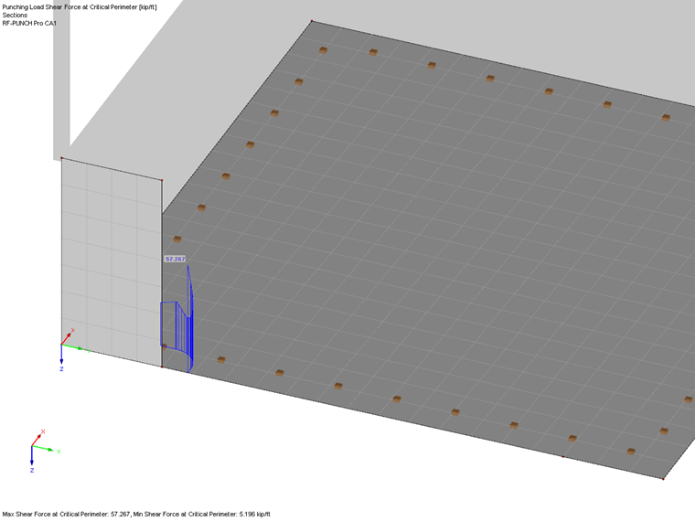
In contrast to single columns (or nodal supports), the punching load for wall ends and wall corners cannot be derived directly from the column axial force (or support force). In RF-PUNCH Pro, the shear force vmax,b is analyzed in the connected plate and the punching load is determined from the shear force in the critical perimeter.
This technical article deals with this topic and describes the options available in the "1.5 Punching Nodes" window and the general procedure for determining the load.
Surface Internal Forces in RFEM
Basically, it should be noted first that the punching load VEd is not determined from a support force of a line support or a normal or membrane force of a wall; the shear forces are evaluated in the plate analyzed for punching.
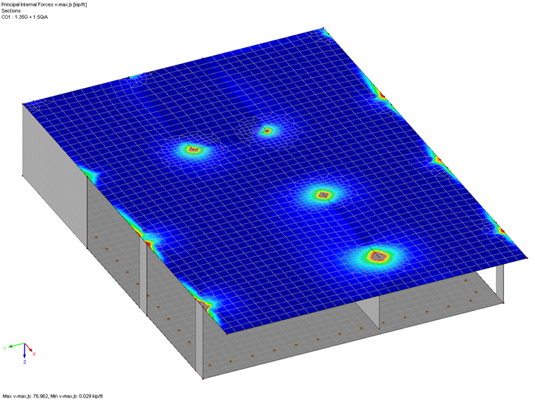
For this, the principal internal force vmax,b from RFEM is used, which is available in the results of the load cases, the load combinations, or the result combinations. How to define vmax,b is described in [1], Section 8.16. Thus, the following results:
Alternatively, this chapter can be found in the RFEM 5 Online Manual.
Influence of Singularities
If there is a singularity location or a peak value in the shear force distribution at a punching point to be verified, this also has an influence on the determined punching load VEd in the critical perimeter.
In the following example, the punching in a floor slab at a wall end will be analyzed. RF-PUNCH Pro uses the main internal force vmax,b in the floor slab. See Image 02 below.
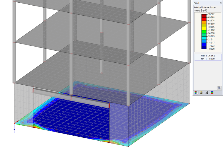
The problem here is that the FE mesh was generated as too coarse and the critical perimeter runs through the peak values of the shear force vmax,b.
The module detects the insufficient FE mesh and displays the corresponding warning No. 56.
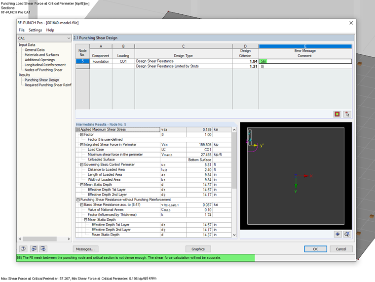
An optional FE mesh refinement refines the mesh that is too coarse in the area of the punching point, resulting in message No. 56. However, the FE mesh refinement can lead to an increase of the peak value of the shear force in the critical perimeter so that the determined value of the punching load VEd is also negatively influenced and thus increased.
If the peak value of the shear force in the critical perimeter is negatively influenced by the application of an FE mesh refinement, it is often advisable to check the entered model with regard to the modeling. In [2], various "sources of error" are discussed, which significantly influence the distribution of internal forces in the surface and thus the punching load VEd determined in RF-PUNCH Pro.
Optimizing Model with Regard to Geometry
In this example, the distribution of shear forces in the slab and finally in the critical perimeter can be achieved by a "more realistic" representation of the floor slab. The first model design sets the boundary lines of the floor slab in the system axes of the rising walls. The second design does not set the edge of the floor slab on the system axes of the walls, but displays it according to the "real" edge of the floor slab. In this way, you can significantly influence the distribution of shear forces in the critical perimeter.
Image 05 below clearly shows the comparison between the two mentioned design checks.
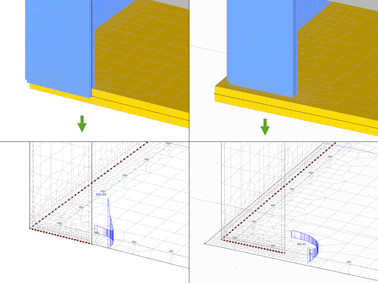
Compared to the first option, this also has the advantage that the more realistic distance to the outer edge of the floor slab is also automatically detected in RF-PUNCH Pro and thus the length of the critical perimeter is applied more favorably.
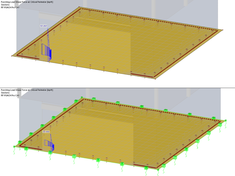
Optimizing Model with Regard to Support
Another option to favorably influence the distribution of shear forces in the considered floor slab is the differentiated consideration of the applied surface elastic foundation.
In RFEM, a constant spring is usually applied as an elastic foundation over the entire floor slab. In addition to the constant spring, RFEM offers other options to represent the surface foundation more favorably.
One possibility is the application of edge or corner springs, which can favorably influence the distribution of shear forces in the floor slab. This topic is covered by this Technical Article, which explains the theoretical background of the (modified) subgrade reaction analysis.
The following graphic shows the comparison of the shear forces in the perimeter without (in the image above) and with (in the image below) applied edge springs on the model with an extended edge.
As an option to the model with edge springs, you can utilize the RF-SOILIN add-on module to get a more realistic approach of the surface foundation, which can also have a positive effect on the distribution of shear forces in the critical perimeter.
Settings in RF-PUNCH Pro
By default, the punching load in RF-PUNCH Pro is determined on the "Unsmoothed shear force distribution along the control perimeter". With the previously mentioned optimizations, this option should always be possible in Window 1.5 of the add-on module. However, if a peak value of the shear force in the critical perimeter is still determined despite the mentioned optimizations, the "Smoothed shear force distribution along the control perimeter" option is also available to the user.

When applying the averaged shear force in the critical perimeter, it is also necessary to consider the influence of the load increase factor β, which can be determined, for example, by means of the sector model. Another Technical Article discusses this topic.
Summary
You should always check the size of the acting punching load in the case of large design ratios for punching design on wall ends or wall corners.
In this context, it is always necessary to pay attention to the distribution of the shear forces in the critical perimeter and to check whether adjustments or optimizations on the model may result in a more favorable distribution of the shear force vmax,b in the slab.
However, the mentioned optimizations with regard to the modeling and support cannot represent a generally valid instruction, but must always be evaluated individually, depending on the situation, and implemented in a modified way that is adjusted to the respective model.