6 Results
View results:
Sort by:

The fatigue design according to EN 1992-1-1 must be performed for the structural components subjected to large stress ranges and/or many load changes. In this case, the design checks for the concrete and the reinforcement are performed separately. There are two alternative design methods available.
At the end of the topic on the design of welds on runway beams - after the technical articles about the rail weld seam in the ultimate limit state and the limit state of fatigue - a technical article about web fillet welds now follows. Both the ultimate limit state and the fatigue limit state are considered.
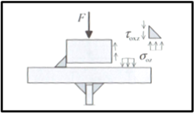
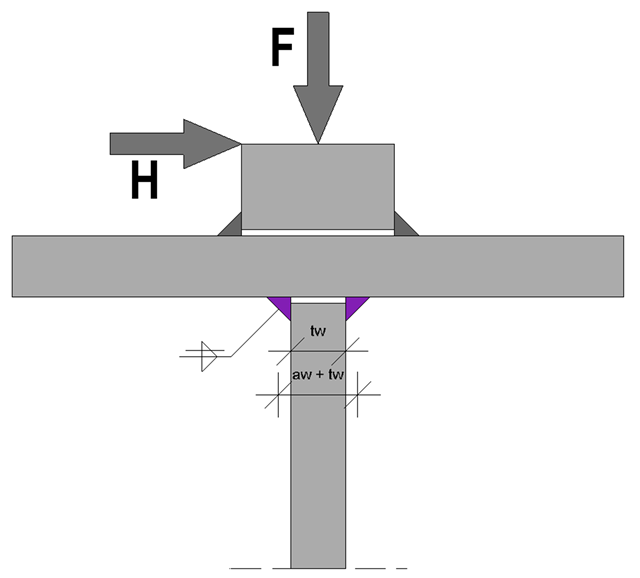
Based on the technical article about the ultimate limit state design of rail welds, the following explanation refers to the process of fatigue design of rail welds. In particular, this article explains in detail the effects of considering an eccentric wheel load of 1/4 of the rail head width.
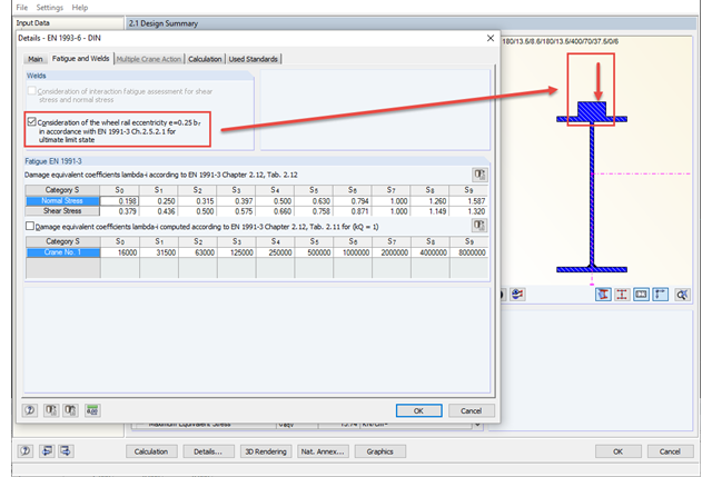
The eccentric wheel load application of 1/4 of the rail head width has to be considered only for fatigue design from damage class S3 according to DIN EN 1993‑6. An additional input option in detail settings allows you to consider this eccentricity for fatigue design at the ultimate limit state as well. By selecting this option, the design with the eccentric load applied is always considered without regard to the damage class.
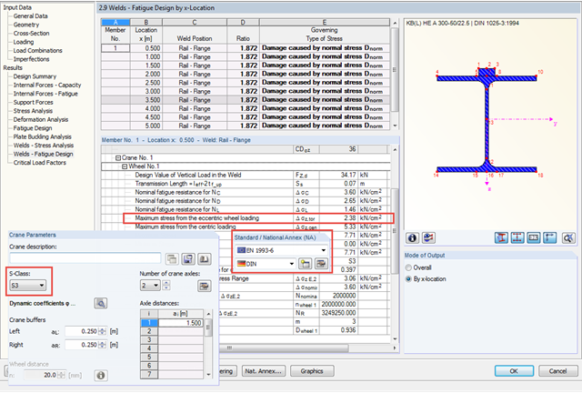
In CRANEWAY, the eccentric wheel loading of 1/4 of the rail head width is used for the fatigue design of welds as well as for craneway girder design according to the National Annex of Germany and as of damage class S3.
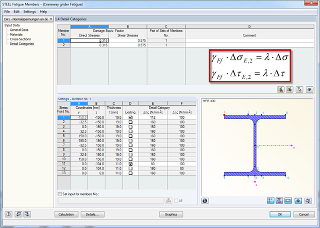
Damage equivalent factors depend on the respective components to be designed in RF‑/STEEL Fatigue Members, and they are explained in the corresponding standards. The following list shows an overview of the standards describing the calculation of the damage equivalent factors in detail.