


Actions
A fatigue assessment is generally required only for those components of the crane supporting structure that are subject to stress variations from vertical crane loads ([2], Section 9.1 [3]). The accompanying note in the standard says that the stress variations due to lateral crane loads are usually negligible. However, they should be taken into account in the case of connection design or a higher number of multiple acceleration and braking actions. Thus, only vertical wheel loads result, which should be modified by the corresponding dynamic factors in accordance with [3], Section 2.12.1 (7).
Dynamic impact factors for modification of vertical wheel loads:
φfat,1 = (1 + φ1) / 2
φfat,2 = (1 + φ2) / 2
Stresses Due to Wheel Loads
In contrast to the ultimate limit state, the stresses refer to the angle leg of the weld in the case of the fatigue design. It is necessary to consider the stresses σ due to wheel load as well as the local and global shear stresses due to the shear force in compliance with [4], Section 5 (6).
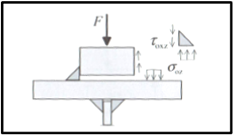
According to [2], the fatigue design of welds should consider the eccentric wheel load of ¼ of the rail head width from the crane damage class of S3 on ([2], Section 9.3.3 [1]). Therefore, if the crane on the crane runway has damage class ≥ S3, the local stresses due to the wheel loads must be determined on the upper flange, including the component from the eccentric wheel load. A simple engineering model for determining the increased wheel load is displayed in [1].

For calculating shear stresses, the local shear stress may be determined using 20% of the vertical stress due to the wheel load, according to [2], Section 5.7.2 (1). Furthermore, the global shear stresses due to the shear force difference of a crane passage ∆V should be applied.
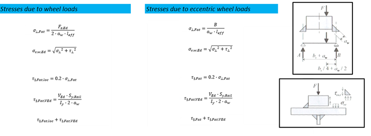
For both the calculation of the wheel load stresses and the determination of the cross‑section properties, the height of the worn‑out crane rail may be set at 12.5% according to [2], Section 5.6.2 (3). The effective load application length is calculated in the same way as in the ultimate limit state design.
Fatigue Limit State Design
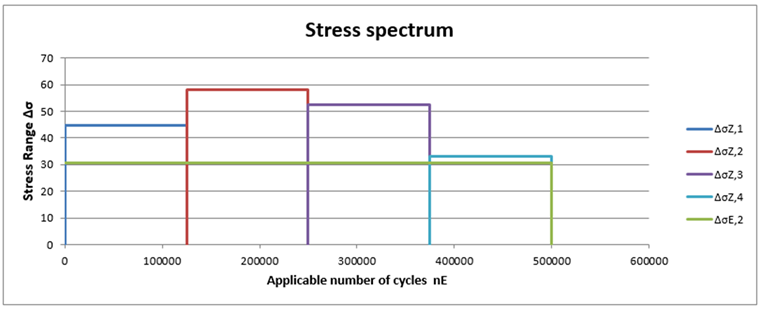
The fatigue design is performed using the stress range spectrum resulting from the structural analysis. The stress ranges result from the global stresses as follows:
∆σ = σmax − σmin
∆τ = τmax − τmin
For local stresses, the stress ranges are the corresponding maximum values, as the minimum values are 0.
Damage Equivalent Stress Range
The task is to convert a multi‑level stress spectrum into a single‑level spectrum with the same damage and to determine the resulting damage equivalent stress range related to 2 ⋅ 106 stress cycles.
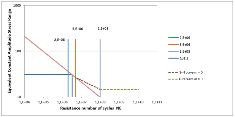
Using the normalized S‑N curves (slope m = 3 for longitudinal stresses and slope m = 5 for shear stresses) and the maximum numbers of working cycles depending on the crane damage class according to [3], Table 2.11, the following formulas can be derived.
Calculation of damage equivalent stress range:
Graphical representation using the selected S‑N curve gives the following diagram:
Now, using the design constructional details, the weld, and the related notch category (Δσc and Δτc), the final design can be performed. The constructional details are shown in [4], Tables 8.1 through 8.10. Table 8.10, in particular, includes some details of the crane girder.
The partial factors depend on the planned inspection intervals and result from [4], Table 3.1 and [2], NA/Table NA.3.: NA.3:
According to [4], Section 5 (6), the interaction is not performed for the weld design.