
With the Concrete Design add-on, you can perform the fatigue design of members and surfaces according to EN 1992‑1‑1, Chapter 6.8.
For the fatigue design, you can optionally select two methods or design levels in the design configurations:
- Design Level 1: Simplified design according to 6.8.6 and 6.8.7(2): The simplified design is performed for frequent action combinations according to EN 1992‑1‑1, Chapter 6.8.6 (2), and EN 1990, Eq. (6.15b) with the traffic loads relevant in the serviceability state. A maximum stress range according to 6.8.6 is designed for the reinforcing steel. The concrete compressive stress is determined by means of the upper and lower allowable stress according to 6.8.7(2).
- Design Level 2: Design of damage equivalent stress acc. to 6.8.5 and 6.8.7(1) (simplified fatigue design): The design using damage equivalent stress ranges is performed for the fatigue combination according to EN 1992‑1‑1, Chapter 6.8.3, Eq. (6.69) with the specifically defined cyclic action Qfat.

- Determination of longitudinal, shear, and torsional reinforcement
- Representation of minimum and compression reinforcement
- Determination of neutral axis depth, concrete and steel strains
- Design of member sections affected by bending about two axes
- Design of tapered members
- Design of RSECTION cross-sections (see this Product Feature)
- Determination of deformation in state II; for example, according to EN 1992‑1‑1, 7.4.3, and ACI 318‑19 24.2.3, Table 24.2.3.5
- Considering tension stiffening
- Considering creep and shrinkage
- Fatigue design according to EN 1992‑1‑1, Section 6.8 (see this Product Feature)
- Simplified fire resistance design according to EN 1992‑1‑2 for Columns (Section 5.3.2) and Beams (Section 5.6) (see this Product Feature)
- Seismic design according to EC 8 (see this Product Feature)
- Precise breakdown of reasons for failed design
- Design details of all design locations for better traceability of reinforcement determination
- Optional cross-section optimization
- Visualization of concrete section with reinforcement in 3D rendering
- Creation of 2D interaction diagrams; for example, M-N diagram
- Visualization of section resistance in 3D interaction diagram
- Output of moment-curvature diagram

- Free definition of two reinforcement layers
- Design alternatives to avoid compression or shear reinforcement
- Design of surfaces as deep beams (theory of membranes)
- Option to define basic reinforcements for top and bottom reinforcement layers
- Free definition of provided surface reinforcement
- Result output in points of any selected grid
- Design with design moments at column edges
- Determination of deformation in state II; for example, according to EN 1992‑1‑1, 7.4.3, and ACI 318‑19 24.2.3, Table 24.2.3.5
- Considering tension stiffening
- Considering creep and shrinkage
- Fatigue design according to EN 1992‑1‑1, Chapter 6.8 (see this Product Feature)
- Design of a shear joint between the web and flange of ribs
- Optional pure slab or wall design of surfaces for a 2D model type
- Precise breakdown of reasons for failed design
- Design details of all design locations for better traceability of reinforcement determination

- Cross-section optimization
- Transfer of optimized sections to RFEM/RSTAB
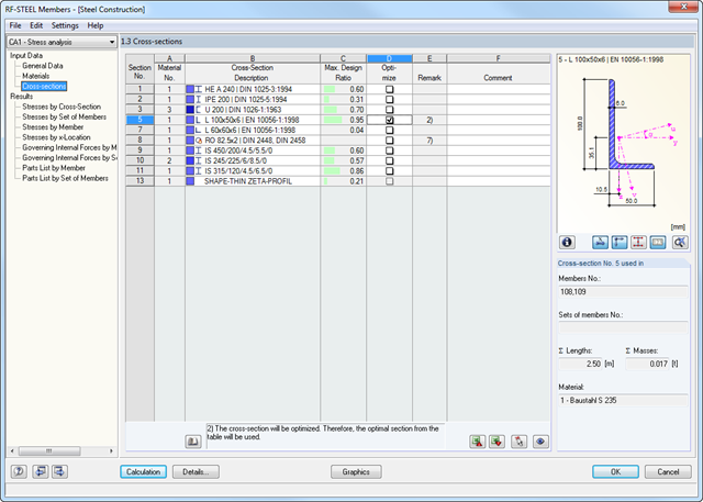
- Design of any thin-walled section from RSECTION
- Representation of a stress diagram on a section
- Determination of normal, shear, and equivalent stresses
- Output of stress components for the individual member internal force types
- Detailed representation of stresses in all stress points
- Determination of the largest Δσ for each stress point (for example, for fatigue design)
- Colored display of stresses and design ratios for a quick overview of the critical or oversized zones
- Output of parts lists
- Cross-section optimization
- Transfer of optimized sections to RFEM/RSTAB
- Design of any thin-walled cross-section from SHAPE-THIN
- Representation of a stress diagram on a section
- Determination of normal, shear, and equivalent stresses
- Stress results of individual internal forces types
- Detailed representation of stresses in all stress points
- Determination of the largest Δσ for each stress point (for example, for fatigue design)
- Colored display of stresses and design ratios for a quick overview of the critical or oversized zones
- Parts lists and quantity surveying
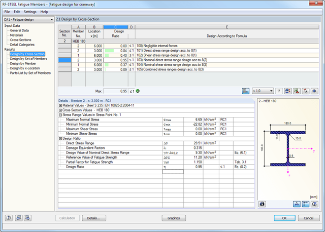
The fatigue strength design is based on the analysis using damage equivalent factors. The damage equivalent stress ranges ΔσE,2 and ΔτE,2 related to 2*106 stress cycles have to be compared to the limit values of the fatigue strength ΔσC or ΔτC for 2*106 stress cycles of the corresponding detail, taking into account the partial safety factors.
In this way, the individual design requirements are specified. Separate design cases enable flexible analysis of selected members, sets of members, and actions, as well as of individual cross‑sections. Design-relevant parameters such as B. selecting the design concept as well as partial safety factors can be defined freely.
- Craneway and weld stress analysis
- Craneways and weld fatigue design
- Deformation,
- Plate buckling analysis for wheel load introduction
- Stability analysis for lateral torsional buckling according to the second-order analysis of torsional buckling (1D FEA element)
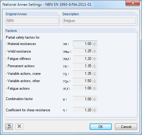
For the design according to Eurocode 3, the following National Annexes are available:
-
 DIN EN 1993-6/NA:2010-12 (Germany)
 -
 NBN EN 1993-6/ANB:2011-03 (Belgium)
 -
 SFS EN 1993-6/NA:2010-03 (Finland)
 -
 NF EN 1993-6/NA:2011-12 (France)
 -
 UNI EN 1993-6/NA:2011-02 (Italy)
 -
 LST EN 1993-6/NA:2010-12 (Lithuania)
 -
 NEN EN 1993-6/NB:2012-05 (Netherlands)
 -
 NS EN 1993-6/NA:2010-01 (Norway)
 -
 SS EN 1993-6/NA:2011-04 (Sweden)
 -
 CSN EN 1993-6/NA:2010-03 (Czech Republic)
 -
 BS EN 1993-6/NA:2009-11 (United Kingdom)
 -
 CYS EN 1993-6/NA:2009-03 (Cyprus)
In addition to the National Annexes listed above, you can also define a specific NA, applying user-defined limit values and parameters.
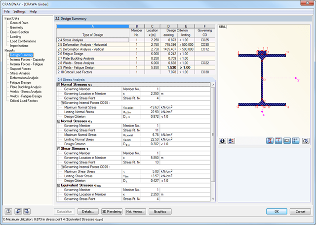
All results are arranged in result windows sorted by different topics. The design values are illustrated in the corresponding cross-section graphic. The design details cover all intermediate values.
General Stress Analysis
CRANEWAY performs the general stress analysis of a craneway girder by calculating the existing stresses and comparing them with the limit normal, limit shear, and limit equivalent stresses. Welds are also subjected to the general stress analysis with regard to parallel and vertical shear stresses and their superposition.
Fatigue Design
Fatigue design is performed for up to three cranes operating at the same time, based on the nominal stress concept according to EN 1993-1-9. In the case of fatigue design according to DIN 4132, a stress curve of crane passages is recorded for each stress point and evaluated according to the Rainflow method.
Buckling Analysis
Buckling analysis considers the local introduction of wheel loads according to the EN 1993-6 or DIN 18800-3 standards.
Deformation,
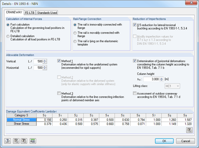
Deformation analysis is performed separately for the vertical and horizontal directions. The available related displacements are compared to the allowable values. You can specify the allowable deformation ratios individually in the calculation parameters.
Lateral-torsional buckling analysis
The lateral-torsional buckling analysis is performed in accordance with the second-order analysis for torsional buckling considering imperfections. The general stress analysis has to be fulfilled with the critical load factor greater than 1.00. As a result, CRANEWAY displays the corresponding critical load factor for all load combinations of the stress analysis.
Support forces
The program determines all support forces on the basis of the characteristic loads, including dynamic factors.
During the calculation, crane loads are generated in predefined distances as load cases of the crane runway. The load increment for cranes moving across the crane runway can be set individually.
The program analyzes all combinations of the respective limit states (ULS, fatigue, deformation, and support forces) for each crane position. In addition, there are comprehensive setting options for specification of the FE calculation, such as length of finite elements or break-off criteria.
The internal forces of a crane runway girder are calculated on an imperfect structural model according to the second-order analysis for torsional buckling.
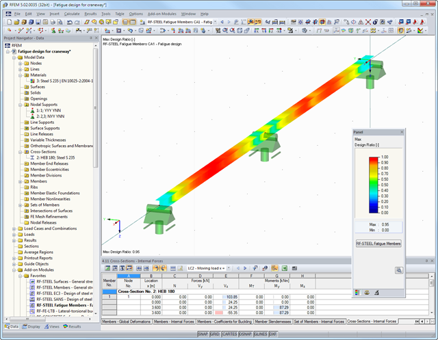
After the calculation, the module displays results in clearly arranged result tables. All intermediate values (for example, governing internal forces, adjustment factors, and so on) can be included in order to make the design more transparent. The results are sorted by load case, cross-section, set of members, and members.
If the analysis fails, the affected cross-sections can be modified in an optimization process. It is also possible to transfer the optimized cross-sections to RFEM/RSTAB for a new calculation.
The design ratio is represented with different colors in the RFEM/RSTAB model. This way, you can quickly recognize critical or oversized areas of the cross-section. Furthermore, result diagrams displayed on the member or set of members ensure targeted evaluation.
In addition to the input and result data, including design details displayed in tables, you can add all graphics into the printout report. This way, comprehensible and clearly arranged documentation is guaranteed. You can select the report contents and extent specifically for the individual designs.
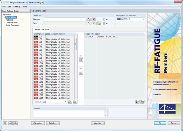
After opening the add-on module, it is necessary to define designed members/sets of members, load cases, load or result combinations for the fatigue strength design.
The materials from RFEM/RSTAB are preset and can be adjusted in RF-/STEEL Fatigue Members. The material properties listed in the respective standard are included in the material library.
The design requires damage equivalent factors as well as detail categories on the designed stress points to be considered in the calculation.
.png?mw=640&hash=721e09a7520480378145fa75eaabf5a5bed8f7e3)
- Full integration in RFEM/RSTAB including import of all relevant information and internal forces
- Determination of stress ranges for the available load cases and load or result combinations
- Free assignment of detail categories on the available stress points of the cross-section
- User-defined specification of damage equivalent factors
- Design of members and sets of members according to EN 1993-1-9
- Optimization of cross-sections with the option to transfer the data to RFEM/RSTAB
- Detailed result documentation with references to design equations used
- Various filter and sorting options of results, including result lists by member, cross-sections, x-location, or by load case, load and result combination
- Visualization of the design criterion on RFEM/RSTAB model
- Data export to MS Excel