Hall with glulam trusses, reinforced concrete columns, and membrane roof
Model Used in
- Eurocode 5 | Timber Structures According to DIN EN 1995-1-1
- Eurocode 5 | Timber Structures According to DIN EN 1995-1-1
- Eurocode 5 | Timber Structures According to DIN EN 1995-1-1
- Eurocode 5 | Timber Structures According to DIN EN 1995-1-1
- Eurocode 5 | Timber Structures According to EN 1995-1-1
- Eurocode 5 | Timber Structures According to DIN EN 1995-1-1
- Eurocode 5 | Timber Structures According to DIN EN 1995-1-1
- Eurocode 5 | Timber Structures According to DIN EN 1995-1-1
- Eurocode 5 | Timber Structures According to DIN EN 1995-1-1
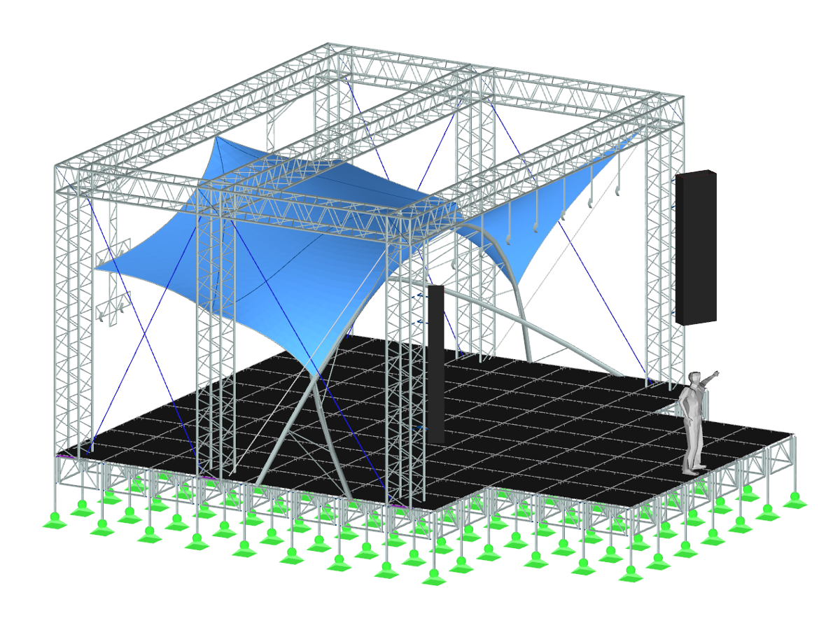
Hall with Membrane Roof
| Number of Nodes | 129 |
| Number of Lines | 199 |
| Number of Members | 195 |
| Number of Surfaces | 26 |
| Number of Solids | 0 |
| Number of Load Cases | 3 |
| Number of Load Combinations | 0 |
| Number of Result Combinations | 0 |
| Total Weight | 136.247 tons |
| Dimensions (Metric) | 17.500 x 7.978 x 30.000 m |
| Dimensions (Imperial) | 57.41 x 26.17 x 98.43 feet |
You can download this structural model to use it for training purposes or for your projects. However, we do not assume any guarantee or liability for the accuracy or completeness of the model.
Related Models