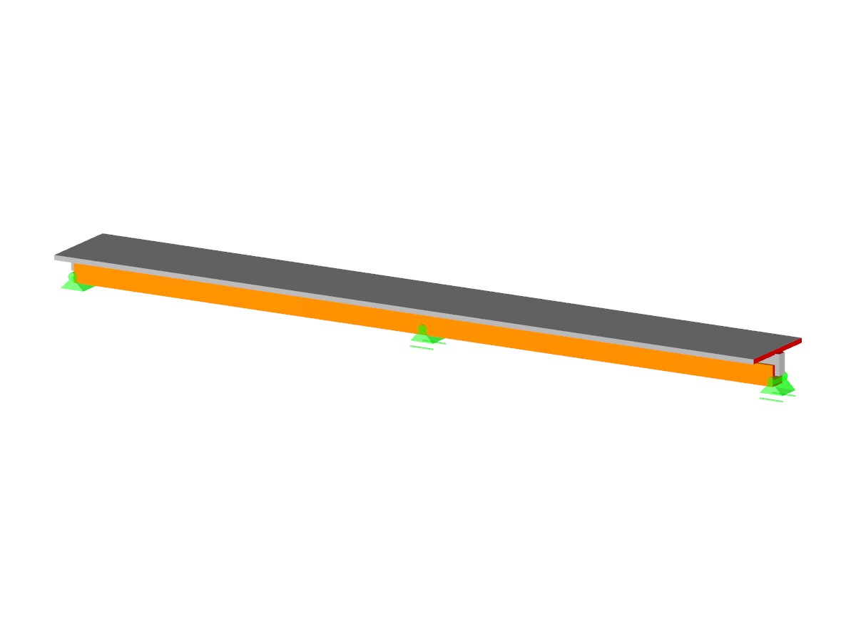
This model shows how the resulting deformation of timber beams and sets of members is analyzed precisely in the RF-/TIMBER Pro, RF-/TIMBER AWC, and RF-/TIMBER CSA add-on modules. The effects of deformations are explained in detail based on the represented SLS design. It is ideal for evaluating the deformation conditions of beams in timber structures.
Model Used in
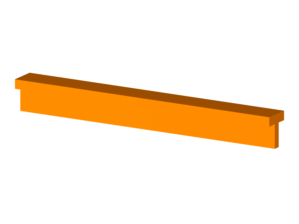
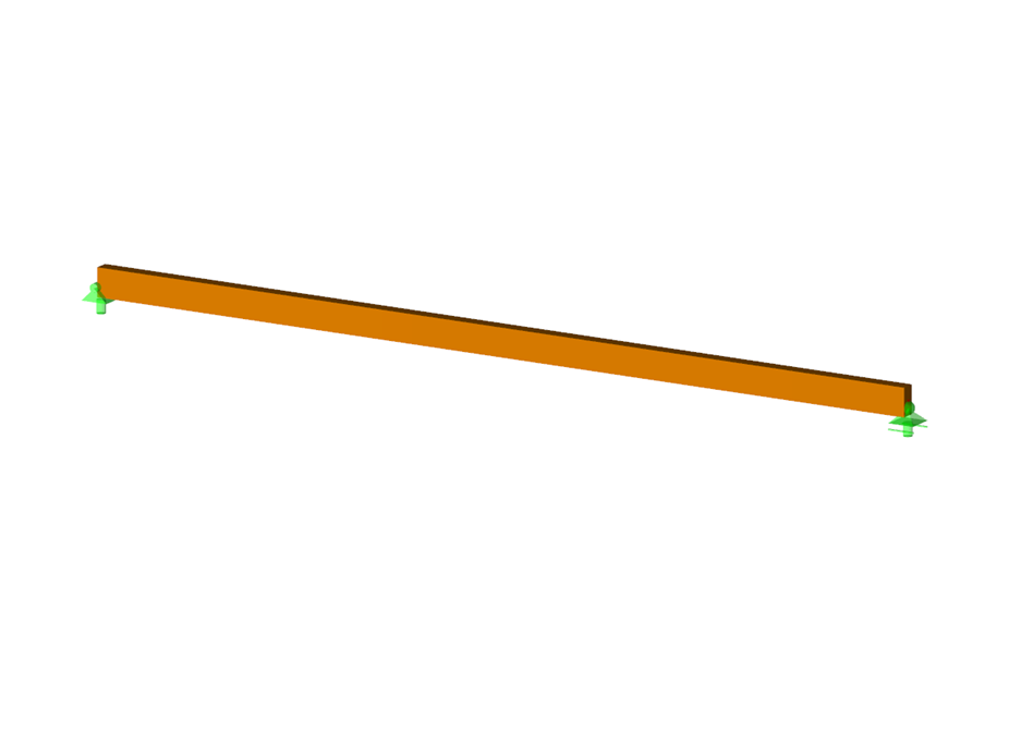
Deformation Analysis of Timber Beam
| Number of Nodes | 2 |
| Number of Members | 1 |
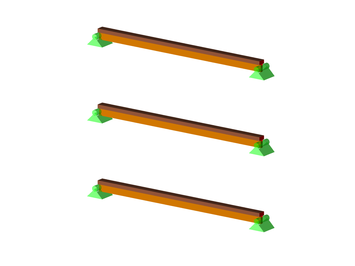
| Number of Load Cases | 1 |
| Number of Load Combinations | 4 |
| Number of Result Combinations | 4 |
| Total Weight | 0.050 t |
| Dimensions (Metric) | 6.313 x 0.313 x 0.313 m |
| Dimensions (Imperial) | 20.71 x 1.03 x 1.03 feet |
| Program Version | 8.25.01 |
You can download this structural model to use it for training purposes or for your projects. However, we do not assume any guarantee or liability for the accuracy or completeness of the model.
Related Models
.png)