


Locally sourced stonework of all sizes allows the structure’s exterior to blend seamlessly with the desert’s red rock surroundings, including the property entrance’s semicircular stone structure, to give the residence its name. The house includes two half-circle wings on either side of a rectangular glass box entryway, complete with a suspended glass staircase.
Project Details
The entryway’s glass staircase, suspended on steel rods, is perhaps the main focal point and most remarkable engineering feat throughout the house. Stutzki Engineering, based in Milwaukee, WI, USA, was awarded the uniquely challenging engineering design role for this project. The curved staircase's crystalline treads appear to be floating among the massive entry windows and decorative red rock interior walls.
When traveling up the left side of the staircase, the treads are securely yet delicately fastened to the interior stone. The staircase’s right side, however, is entirely suspended from thin steel rods spanning from multiple points on each tread to the ceiling above. This design did not require any structural components under the staircase, which gives the glass stairway its floating yet effortless appearance.
Structure Details
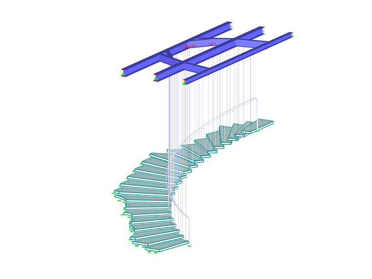
The structure, as can be seen from the photos, is an unusual assembly of glass treads, tension rods (cables), steel beams, and delicate custom-fabricated connectors made of stainless steel. These connectors, fabricated by the company Tripyramid (MA), provide adjustability and strength at the same time. They tie each glass tread to the rocks on one side, and to the tension rods along the inner circle of the stair. The intricate detailing of these connectors minimizes local stress peaks in the glass. Each detail was modeled in RFEM according to its unique function and release-details of degrees of freedom.
The vibration analysis showed that the construction frequency was high enough so that people walking on the staircase will not experience an unpleasant feeling. The tension in the rods is generated by the weight of the glass, so it is fairly low. The handrail was installed as a safety feature, not for structural reasons.
A preliminary simplified analysis was done with just one typical tread and a few corresponding tension rods. The decision to build a complete model of the whole staircase was not due to a beginner’s take on structural analysis; it was necessary in order to fully understand the lateral stability and dynamic behavior. RFEM once again proved its robust and accurate modeling and solving capabilities, although this model was an assembly of materials and details of which the stiffness numbers are many magnitudes apart.
As presented at other locations [1], this structure is a combination of art and technology, qualifying as a type of space frame with tension and compression members.
[1] Stutzki, C. (2019). Steel- and Glass Spaceframes between Art and Technology. In: Proceedings of the IASS Annual Symposium 2019, Barcelona, Spain. ISSN 2518-6582 (online).
| Location | Sedona, Arizona, USA |
| Owner | Private Owner |
| Structural Design | Stutzki Engineering |
| Architecture | SWABACK pllc www.swaback.com |
| Construction Company | 180 Degrees Design + Build www.180degreesinc.com |


