We provide hints and tips to help you get started with the basic program RFEM.
Home Support & Learning Learning Videos FAQ 003508 | How can I apply a load on a partial area of a rotationally symmetric structural component only?
FAQ 003508 | How can I apply a load on a partial area of a rotationally symmetric structural component only?
Video
First Steps with RFEM
Question
How can I apply a load on a partial area of a rotationally symmetric structural component only?Answer
A free variable load allows you to apply a load on surfaces that can vary in height and perimeter.
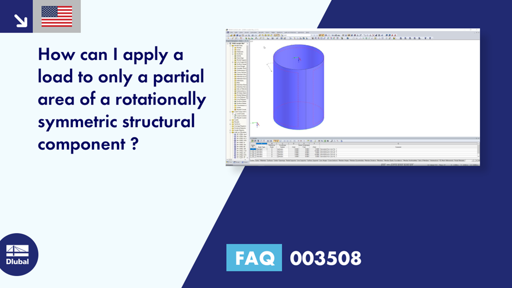
Figure 01 shows a circular container that is only loaded by more than a half of the perimeter in the surface normal direction. To define a load varying along the perimeter, it is necessary to activate the "Varying" option" under "Along perimeter." Click the corresponding button to enter the factors for the load including the angles where they occur. Furthermore, you can define the rotation axis. The factor kα creates a reference to the load value p of the initial dialog box.
As an alternative, it is possible to split the surface into the corresponding surface components. Subsequently, you can apply a surface load to the relevant surface components.
The container shown in Figure 01 has been modeled with two partial surfaces in Figure 02. Thus, it is possible to apply the surface load to the container half that should be loaded.
Keywords
Dlubal FAQ Free variable load Cylinder load Container load Frequently Asked Question FAQ about Dlubal Question and Answer about Dlubal
Links
Contact us
Do you have any questions about our products or need advice on selecting the products needed for your projects?
Contact us via our free e-mail, chat, or forum support or find various suggested solutions and useful tips on our FAQ page.
Recommended Events
Eurocode 5 | Timber structures according to EN 1995-1-1
Online Training 03/17/2021 8:30 AM - 12:30 PM CET
Eurocode 3 | Steel structures according to DIN EN 1993-1-1
Online Training 03/18/2021 8:30 AM - 12:30 PM CET
Eurocode 3 | Steel structures according to DIN EN 1993-1-1
Online Training 05/06/2021 8:30 AM - 12:30 PM
Eurocode 2 | Concrete structures according to DIN EN 1992-1-1
Online Training 05/11/2021 8:30 AM - 12:30 PM
Eurocode 5 | Timber structures according to DIN EN 1995-1-1
Online Training 05/20/2021 8:30 AM - 12:30 PM
RFEM | Structural dynamics and earthquake design according to EC 8
Online Training 06/02/2021 8:30 AM - 12:30 PM
Videos
Models to Download
Knowledge Base Articles

New
Saving Parameterized Model as Block
The parameterized input provides the engineer with an efficiency -increasing tool.
Screenshots
Product Features Articles

New
Increased Calculation Performance by Reducing the Nodal Degrees of Freedom
The number of degrees of freedom in a node is no longer a global calculation parameter in RFEM (6 degrees of freedom for each mesh node in 3D models, 7 degrees of freedom for the warping torsion analysis). Thus, each node is generally considered with a different number of degrees of freedom, which leads to a variable number of equations in the calculation.
This modification speeds up the calculation, especially for models where a significant reduction of the system could be achieved (e.g. trusses and membrane structures).
Frequently Asked Questions (FAQ)
- How can I use the COM interface to B. delete all nodes or members in a model?
- Why does the vertical position of a result member in my model have no influence on the bending moment My of the member?
- Is it possible to keep the results from RWIND Simulation when deleting the FE mesh if I only adjust materials or support conditions?
- How do I model a tent roof with two cone tips?
- How can I change the colors of the selection and preselection?
- How are the signs for the release results of a line release and line hinges interpreted?
- How can I create a curved or arched section?
- After the calculation in the RF‑/DYNAM Pro - Equivalent Loads add-on module, the size of my file has increased significantly. The performance has worsened enormously. What could be the reason for this?
- Is it possible to make the generated member loads from area loads via plane to act eccentrically on the member cross-section?
- Why are my imperfections displayed graphically in different ways and can I adjust the display?
Customer Projects