Content:
- Exchange of data from Revit to RFEM via the direct interface link between programs
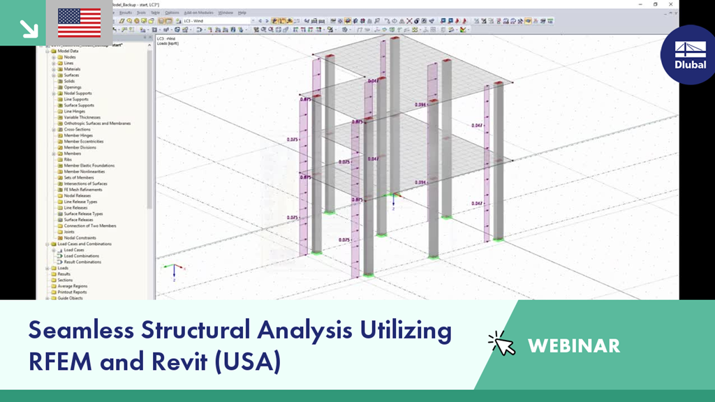
- Finite element analysis and design of a steel and concrete structure in RFEM according to US Standards
- Optimization and modifications in RFEM are integrated back into Revit to allow for an efficient update of the original BIM model
Webinar: Seamless Structural Analysis Utilizing RFEM and Revit (USA)
Links
Do you have any questions?
The fatigue design according to EN 1992-1-1 must be performed for the structural components subjected to large stress ranges and/or many load changes. In this case, the design checks for the concrete and the reinforcement are performed separately. There are two alternative design methods available.
Using an example of a steel fiber-reinforced concrete slab, this article describes how the use of different integration methods and of a different number of integration points affects the calculation result.
When it comes to wind loads on building type structures as per ASCE 7, numerous resources can be found to supplement design standards and aid engineers with this lateral load application. However, engineers may find it more difficult to find similar resources for wind loading on non-building type structures. This article will examine the steps to calculate and apply wind loads as per ASCE 7-22 on a circular reinforced concrete tank with a dome roof.
In order to correctly design a downstand beam or a T-beam in RFEM 6 using the Concrete Design add-on, it is essential to determine the flange widths for the rib members. This article describes the input options for a two-span beam and the calculation of the flange dimensions according to EN 1992-1-1.
There is a known complexity in calculating footfall response on irregular floors or staircases of any type. Footfall Analysis uses the RFEM model and the modal analysis results of RF-DYNAM Pro - Natural Vibrations to predict the vibration levels at all locations on a floor. A rigorous analysis method is essential to enable an accurate investigation of the dynamic behavior of the floor.
The software incorporates the most up-to-date analysis procedures, allowing the user to select between the two most often used calculation methods available, namely the Concrete Centre Method (CCIP-016) and the Steel Construction Institute Method (P354).
- Footfall Analysis links with RFEM, using the model geometry from there, thus the user is not required to create a second model specifically for footfall analysis
- Allows the user to analyze any type of structure for footfall analysis, irrespective of the shape, material, or use
- Quick and accurate predictions of resonant and impulsive (transient) responses
- Cumulative measurement of vibration levels – VDV analysis
- Intuitive output enabling the engineer to advise improvements of critical areas in a cost-effective way
- Pass/fail limit check in accordance with BS 6472 and ISO 10137
- Selection of excitation forces: CCIP-016, SCI P354, AISC DG11 for floors and stairs
- Frequency weighting curves (BS 6841)
- Quick investigation for full model or specific areas
- Vibration Dose Analysis (VDV)
- Adjusting the minimum and maximum walking frequencies as well as the walker’s weight
- User input damping values
- Varying the number of footfalls for resonant response, user input or software calculated
- Environmental response limit based on BS 6472 and ISO 10137
- Overall maximum response factors and critical nodes
- Resonant analysis (maximum response factor, RMS acceleration, critical node, critical frequency)
- Impulsive (transient) analysis (maximum response factor, peak acceleration/velocity, RMS acceleration/velocity, critical node, critical frequency)
- Vibration dose values for both resonant and impulsive analyses
Charts
- Response factor vs walking frequency
- Mass participation vs eigenmodes
- Velocity time history
- 3D incompressible wind flow analysis with OpenFOAM® software package
- Direct model import from RFEM or RSTAB including neighboring and terrain models (3DS, IFC, STEP files)
- Model design via STL or VTP files independent of RFEM or RSTAB
- Simple model changes using Drag and Drop and graphical adjustment assistance
- Automatic corrections of the model topology with shrink wrap networks
- Option to add objects from the environment (buildings, terrain ...)
- Wind load determined over the height of the building, depending on standard-specific parameters (velocity, turbulence intensity)
- K-epsilon and K-omega turbulence models
- Automatic mesh generation adjusted to the selected depth of detail
- Parallel calculation with optimal utilization of the capacity of multicore computers
- Results in just minutes for low-resolution simulations (up to 1 million cells)
- Results within a few hours for simulations with medium/high resolution (1‑10 million cells)
- Graphical display of results on the Clipper/Slicer planes (scalar and vector fields)
- Graphical display of streamlines
- Streamline animation (optional video creation)
- Definition of point and line probes
- Display of aerodynamic pressure coefficients
- Graphical display of turbulence properties in the wind field
- Optional meshing using the boundary layer option for the area near the model surface
- Consideration of rough model surfaces possible
- Optional use of a seond-order numerical Order
- Multilingual user interface (for example, German, English, Spanish, French)
- Documentation possible in the RFEM and RSTAB printout report
Recommended Products for You