


General Parameters
The following general data from ASCE/SEI 7‑16 are required to enter the wind loads on walls and roofs:
- Basic wind speed V (see Section 26.5, Figs. 26.5-1 and 26.5-2)
- Wind directionality factor Kd (see Section 26.6)
- Exposure category B, C, or D (see Section 26.7)
- Topographic factor Kzt (see Section 26.8)
- Ground elevation factor Ke (see Section 26.9)
- Gust-effect factor G (see Section 26.11)
- Enclosure classification (see Section 26.12)
- Mean roof height h (see Section 26.2)
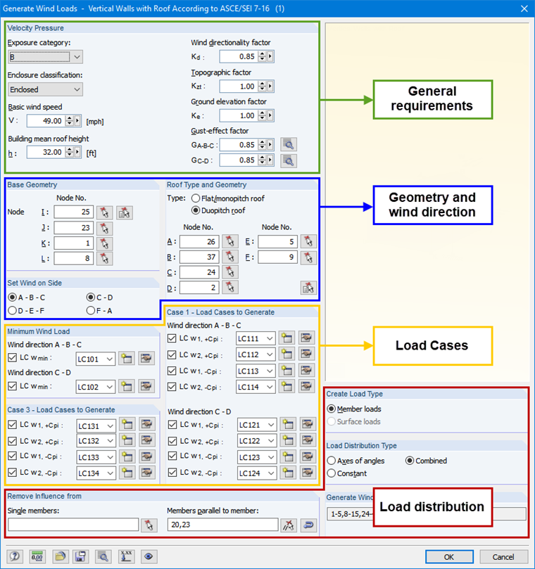
These general parameters for the determination of velocity pressure are required in the upper part of the dialog box (see Image 01).
Geometry and Wind Direction
Next, the base and roof geometry have to be entered (see Image 01 in the middle). In the case of a flat roof, the nodes A and I, B and J, C and K, as well as D and L must rest below each other. In the case of a duopitch roof, the same applies to the nodes A and I, C and J, D and K, and F and L. Furthermore, the wind direction should be set on the respective building side. Due to the various cases (see ASCE/SEI 7‑16, Fig. 27.3-8) to be examined, you must always define two building sides.
Load Cases
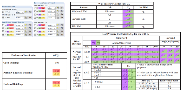
In order to generate the loads, these must be available in load cases. For this, it is necessary to assign the load cases to the respective load situation (see Image 01 at the bottom left and Image 02). The classification is structured as follows:
- Minimum Design Wind Loads for the respective direction according to ASCE/SEI 7‑16 27.1.5
- Case 1: Full design wind pressure acting on the projected area perpendicular to each principal axis of the structure, considered separately along each principal axis.
- Case 3: Wind loading as defined in Case 1, but considered to act simultaneously at 75% of the specified value.
According to ASCE/SEI 7‑16, Table 26.13-1, Note 3, the internal pressure coefficient (GCpi) must be considered positively and negatively in order to take into account the most unfavorable load position. Various signs are indicated by the index +cpi and -cpi in the load cases (see Image 02, highlighted in yellow and red). Since the wind pressure changes quickly between positive and negative values for the wind direction right-angled to the ridge, two values for the external pressure coefficient are specified in ASCE/SEI 7‑16, Fig. 27.3-1. Both must be checked according to Note 3. This is indicated in the dialog box by the index w1 and w2 (see Image 02, highlighted in purple and green). Basically, all constellations have to be analyzed in order to find the most unfavorable state. If you want to exclude the non-governing load cases, you can deactivate the load cases by unchecking the relevant checkbox.
Load Distribution
In the bottom part of the dialog box (see Image 01), you can specify settings regarding the load distribution. This is explained in detail in the RFEM manual [2], Chapter 11.8.