


Member Types and Hinges
When modeling simple member structures, the following member types are usually used.
- Beam member: a rigid member transferring any internal forces and moments
- Truss member: a beam member with a moment release at both ends
- Tension member: a member with stiffness EI failing in the case of compression force
- Compression member: a member with stiffness EI failing in the case of tension force
- Buckling member: a member with stiffness EI failing if the buckling load is exceeded
Further member types are described in the online manual for RFEM:
In addition, nonlinear properties can be set for both members and hinges. This allows you to specify special failure criteria or nonlinear relations between forces and strains. This technical article presents some options for modeling using member types and hinges by describing a simple example.
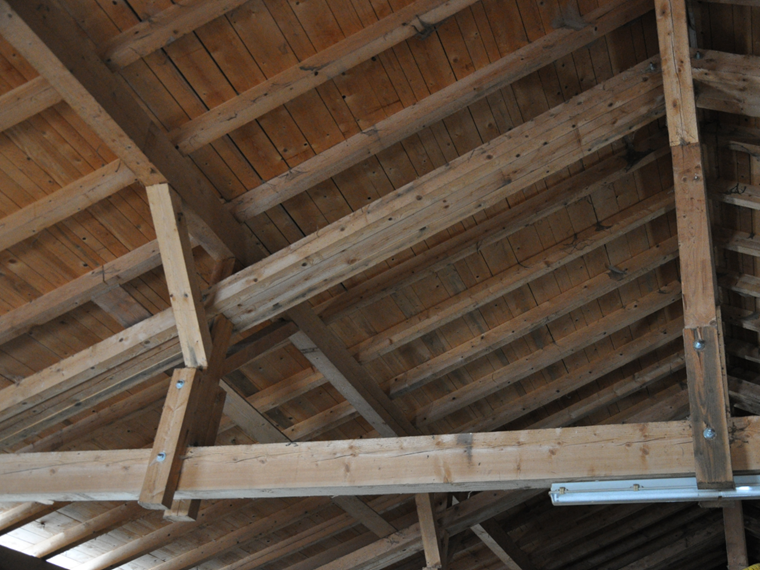
Roof Structure
A barn's roof system, of which the truss-like supporting structure was built in a structurally incorrect way, is the subject of our analysis: A diagonal was "forgotten" for the truss so that visible deformations occurred even under self-weight load. This member, being essential for the structure's load-bearing capacity, was added subsequently. Thus, damage could be avoided.
The RFEM model represents a section of the roof structure. The base purlins are assumed to be fixed supports; the ridge and central purlins are considered to be lateral supports with a small rotational spring. Simplifying the load application, the load is applied by the roof rafters with corresponding application areas. "Self-Weight and Structure" and "Snow" are analyzed as exemplary load cases.
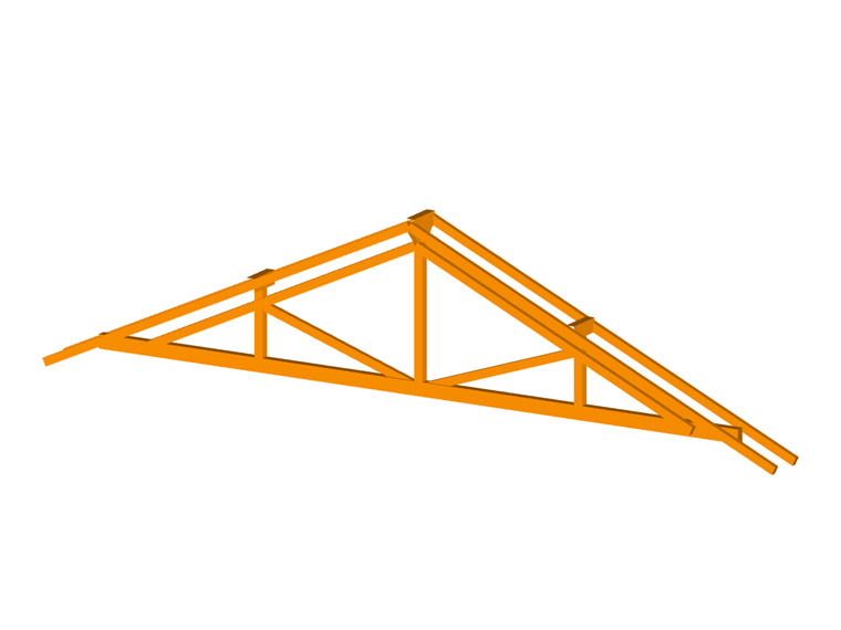
Truss Model with Scissor Hinges
The structural system is modeled with beam members, which are given corresponding hinges at locations with moment releases. A pure truss member model would not be correct, because some members pass through the points of intersection and thus transfer moments. The "Truss (N only)" member type is only used for the two knee braces. The missing diagonals can be represented in the model by the "Dummy" member type. They are not taken into account in the calculation.
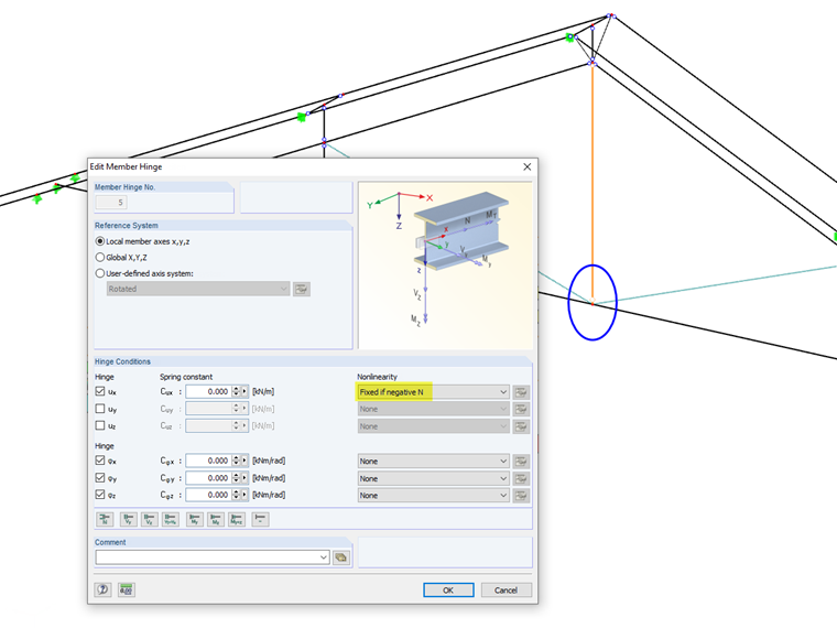
Hinges are usually related to the local xyz member axes. For spatial beam structures, this allows you to control the transfer of forces and moments to the members that are connected to one node. In the model, local moment releases are used for the ends of those members that do not transfer moments due to the simple timber connections - for example, the posts at the top and bottom ends. For continuous members such as the rafters and posts mentioned above, however, scissor hinges are used. They provide the continuous beam effects for the moments on the respective crossing member pairs. Scissor hinges are always related to the global XZY axis system.
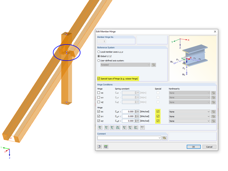
The use of scissor hinges is also described in FAQ 000177 and FAQ 001438:
Certain member types, such as truss or compression members, are provided with hinges by definition so that they do not need to be defined additionally; the corresponding input fields are locked.
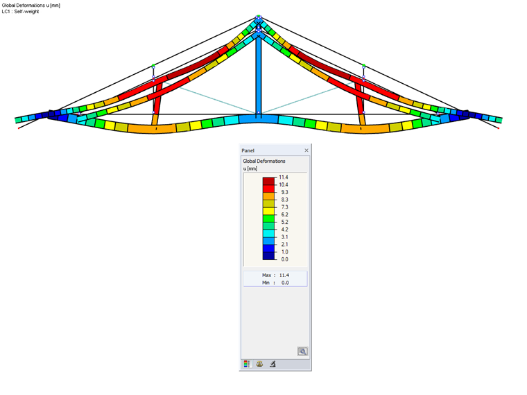
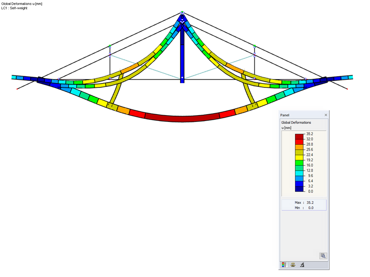
After calculating the model, rather large deformations can be seen for LC 1 (permanent loads).
The calculation of the design combination CO2 ends with an instability message.
Truss Model with Nonlinearly Acting Hinge
In addition, the following scenario is analyzed for this example. If the connection of the center post to the bottom chord was designed as a pure tenon connection, the connection would become loose due to the tensile force in the post. This effect can be considered in the model by a nonlinearly acting axial force release, which allows the connection to become effective only for compressive forces.
LC 1 is calculated in several iterations. Due to the tensile forces in the center post, the connection at the bottom chord is released so that the system is decoupled there.
Alternative modeling could be done in the form of a nodal release (see the online manual).
Model of Renovated Truss
Both dummies are replaced by buckling members in the renovated structure. They act like truss members, but fail for compressive forces beyond the buckling load. The calculation of the design combination CO 2 according to second-order analysis now runs without interruption.
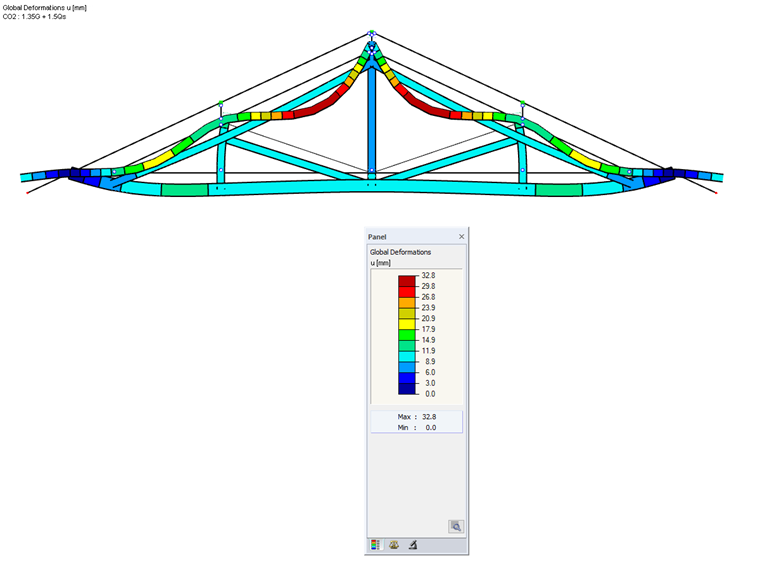
The truss girder's deformation shows the effect of the bracing. The rafters' deflections are caused by the load introduction's modeling that was selected for this section of the structural system. They are not subjects of this analysis.
Conclusion
Using the example of a simple truss girder, we showed how member types and hinges can be used to represent the distribution of internal forces and moments in the model. Scissor hinges play an important role here, making it easier to model beam crossings in timber structures. Nonlinear properties can also be assigned to members and hinges. With dummy members, variants of the model can be analyzed in a time-saving manner.
