


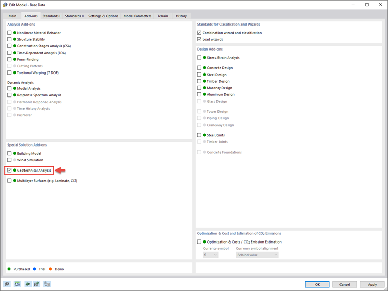
The Geotechnical Analysis add-on allows you to use the properties from soil samples and specific soil material models to represent the interaction between the building and the soil, as well as the influences of the foundation components among themselves. In addition, it offers an extensible library of soil properties, consideration of several soil samples (probes) at different locations, determination of settlements and stress diagrams, and a graphical and tabular display of them.
Practical Example
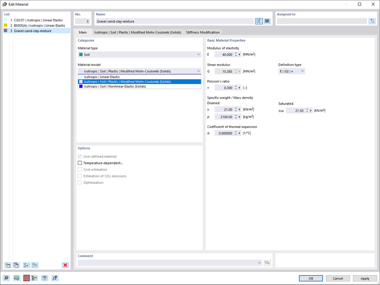
Once the add-on is activated, you can begin your work by defining the soil materials of interest in the Materials dialog box shown in Image 02. In practice, the material properties of the soil must be defined manually since they are specific for each individual project.
This is also possible in RFEM 6, where you can define the properties of diverse soil materials. In addition to the basic material properties (for example, modulus of elasticity, shear modulus, Poisson’s ratio, the specific weight/mass density, coefficient of thermal expansion), you must select the material model to be used for realistic modeling of the soil material behavior.
In the current version of RFEM 6, the Mohr-Coulomb model as well as a nonlinear model with stress- and strain-dependent stiffness are available.
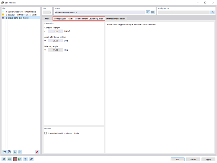
In this example, the modified Mohr-Coulomb is selected to model the behavior of the soil material of interest. Therefore, parameters such as cohesive strength (c), angle of internal friction (φ), and dilatancy angle (ψ) must be assigned in the associated dialog box (Image 03).
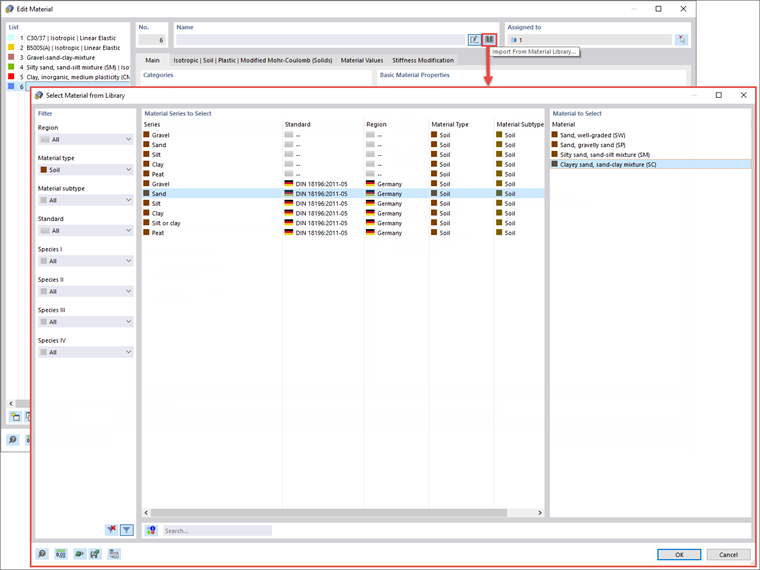
An extensible database is also available to facilitate the selection of the soil material properties. To show this, the other soil materials in this example are defined via the Material Library, as shown in Image 04.
Next, you should define the soil samples by entering the information obtained from the field tests (that is, the characteristics of the soil profile in different positions). The soil samples are available as special objects in RFEM 6.
As Image 05 shows, you can enter soil layers for the individual samples in a clearly arranged dialog box, or by providing the relevant data in the tables. Since the soil material properties have already been defined, you can select the materials directly from the drop-down menu and assign the associated thickness. However, it is also possible to define new materials when defining the layers.
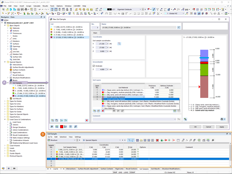
If groundwater is detected through the field tests, you can assign the groundwater level in this dialog box (Image 05). Furthermore, you can define multiple numbers of layers and soil samples that will be used to generate the soil. A corresponding graphical representation supports the definition of separate samples and helps you to check the input.
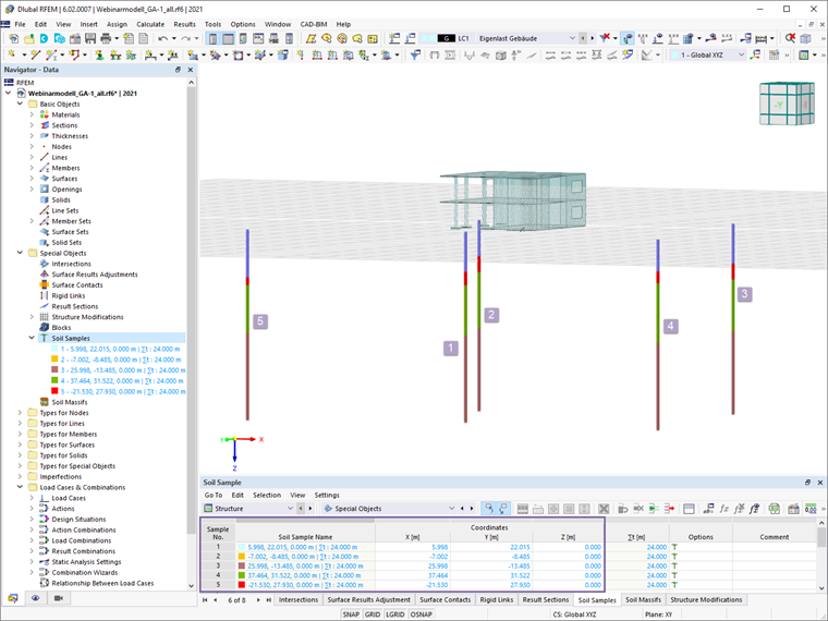
For each individual sample, you should provide the associated coordinates of the RFEM working plane that correspond to the actual field position for which the soil profile has been obtained. This can be done either in the Soil Samples dialog box or in the tables. In the latter, you can copy all the coordinates from a document (for example, an Excel file) and simply paste them. The soil profiles will then be shown in the working window, as in Image 06.
The data in terms of soil samples can now be used to create the soil massif available as a special object both in the Data navigator and in the tables. To be more specific, the soil massif can be generated from the previously defined soil samples, but you can also generate it as a set of soil solids (that is, by defining the soil solids manually and applying them to the massif). In this example, the former option will be used.
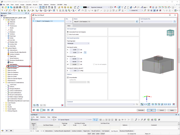
The Soil Massif dialog box is shown in Image 07. To generate the soil massif from soil samples, you should first select the samples of interest. Next, you are asked to define the soil massif geometry by assigning the topology type, the size of the massif, and the coordinates of its center. The depth is assigned automatically, according to the soil sample data.
If necessary, you can rotate the massif about Z. You can also take into consideration the potential presence of groundwater by generating the groundwater level surface. If this option is selected in the dialog box, the groundwater will be shown in the interactive graphical representation.
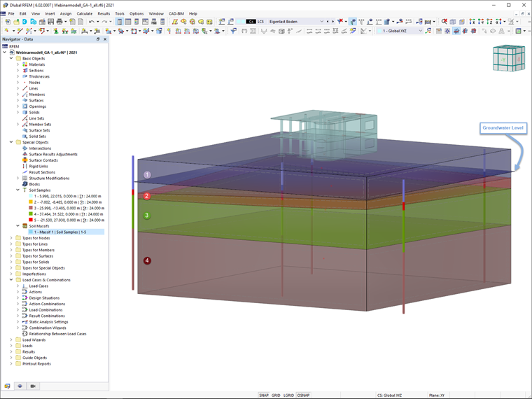
Once the soil massif is generated, it is displayed graphically in the RFEM working window. As shown in Image 08, the massif consists of as many soil solids as there are previously defined layers (4, in this example).
The surfaces between these solids are NURBS surfaces defined with spline functions and approximated through the positions of the layers in the soil samples. If the option to consider groundwater has been selected, the groundwater level is also available in the graphical representation.
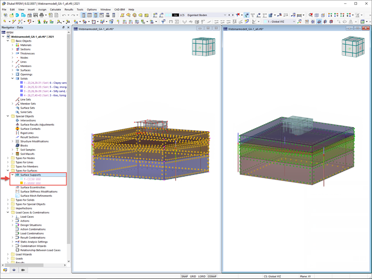
Finally, the supports of the boundary surfaces have been generated via the Types of Surfaces entry of the Data navigator. For instance, you can see that the supports for the horizontal boundary surfaces at the bottom are fixed, whereas sliding is allowed for the surrounding vertical surfaces (Image 09).
Final Remarks
Given that the realistic determination of the soil conditions significantly influences the quality of the structural analysis of buildings, the Geotechnical Analysis add-on is offered in RFEM 6 to determine the soil body to be analyzed. For that purpose, you can provide data obtained from field tests since the add-on allows you to use the properties from soil samples to determine the soil massifs of interest.
Thus, you should assign the material properties, choose the appropriate soil material model, and define the soil profiles in the program. For each soil sample, you are asked to define the soil layers in terms of materials and thickness, groundwater level (if applicable), and the sample’s position in the RFEM working window (corresponding to the actual field position for which the soil profile has been obtained).
The soil is then generated from all entered samples using 3D solids, and it is assigned to the structure using the coordinates.