Practical Example
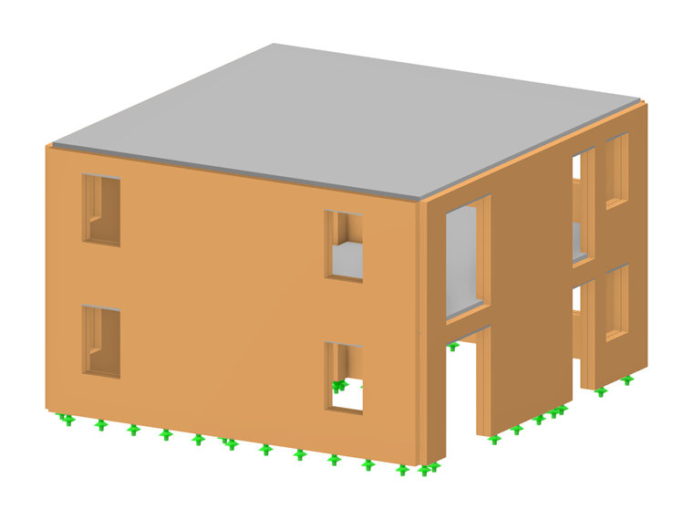
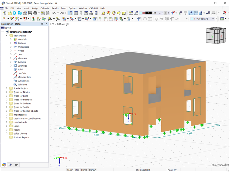
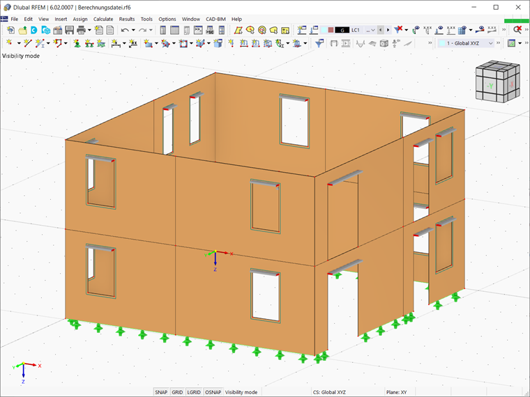
The structure shown as an example in this article consists of reinforced concrete slabs and masonry walls modeled as surfaces in RFEM 6 with corresponding openings for doors and windows (Image 1). The length of the outer walls is 9.880 m along the global Y axis and 9.480 m along the global X axis. The total height of the building is 6.1 m.
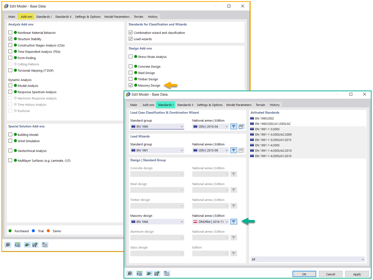
To start working with the Masonry Design add-on, you should first activate it in the model’s Base Data. You can also select the standard for masonry design in the Standards I tab of the same window, as shown in Image 2. The implementation of different standards and associated national annexes for masonry design in RFEM 6 is a work in progress, and thus the associated database will be constantly expanding.
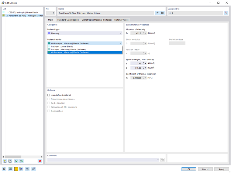
The next step is to define the materials you want to use. To do this, select the Masonry material type in the Main tab of the Materials window. In addition to defining the material and the material properties such as modulus of elasticity, specific weight/mass density, coefficient of thermal expansion and so on, it is necessary to assign the appropriate material model to the material you are defining.
Thus, the orthotropic plastic material model is selected (Image 3) as a relevant representation of the masonry material in terms of calculation and dimensioning in line with the Eurocode.
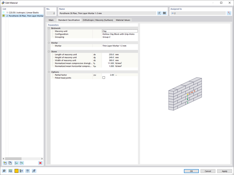
In the Standard Classification tab of the Materials window, you can define the parameters of the combination of materials (that is, brickwork, stone, and mortar) that you want to use.
This information can be found in the manufacturers’ catalogs and it can be inserted in this window (Image 4). You also have the option to define a partial safety factor on the material side and to consider filled head joints (used in case of lintels above openings).
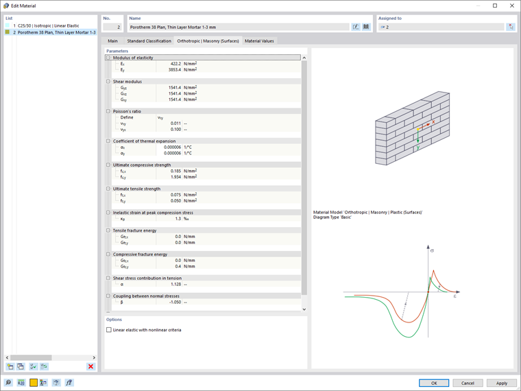
Based on these data, the parameters for the material model are calculated automatically and shown in the next tab of the Materials window (Image 5). These include parameters in both X and Y directions such as modulus of elasticity, Poisson’s ratio, ultimate compressive strength, ultimate tensile strength, coefficient of thermal expansion, and so on. Therefore, it is important that the local Y direction of the walls is the one in which the load is acting.
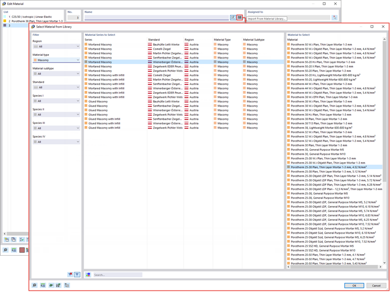
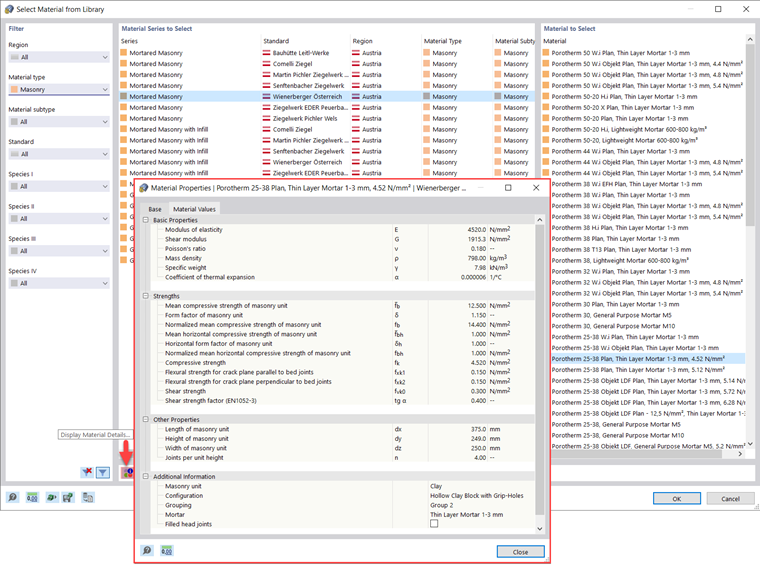
There is another option to define materials: select them directly from the Material Library, which is accessible as shown in Image 6. If you filter the available materials in terms of the “Masonry” material type, you can easily select the material of interest from the RFEM 6 database, which is constantly expanding. For every material in the list, you can display material details as shown in Image 7.
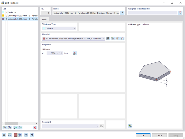
Once the materials are defined, you can create the associated thicknesses as shown in Image 8. In addition to the thickness related to the concrete slabs, two thicknesses of 380 mm and 250 mm are created in this example for the outer and inner walls, respectively. The material of the former is Porotherm 38 Plan, Thin Layer Mortar 1-3 mm, whereas for the latter it is Porotherm 25-38 Plan, Thin Layer Mortar 1-3 mm.
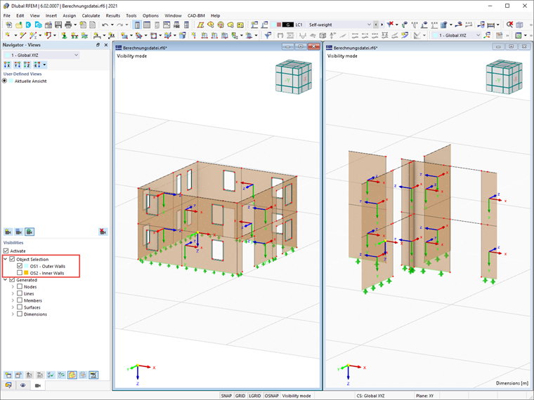
To assign the thicknesses to the corresponding walls in a simple manner, you can create two separate object selections: one for the outer walls and one for the inner walls (by selecting the objects of interest → right click → Create Object Selection). This is shown in Image 9, where you can also see that the local Y axis of the walls is indeed the load-acting direction.
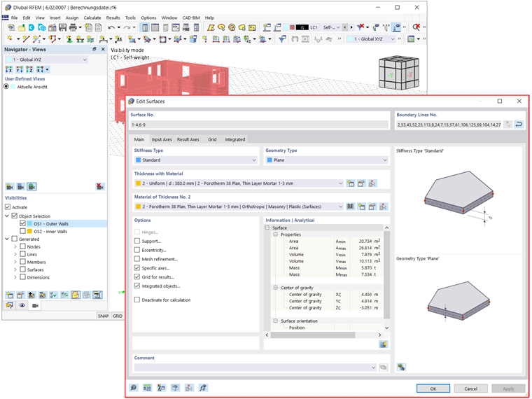
By doing this, you can easily assign the corresponding thicknesses to the outer walls and the inner walls. Image 10 shows the assignment of thickness to the outer walls.
The last step of the modeling process that will be discussed in this article is the special attention required by the openings of the structure. This is due to the very low tensile strength of the material, which might negatively affect the upper parts of the openings.
To avoid this, you should define new member elements and place them above openings such as doors and windows. In this example, concrete beams are created and assigned to all window and door openings, as shown in Image 11.
Final Remarks
The Masonry Design add-on allows you to model and design masonry structures in RFEM 6. With the implementation of a nonlinear material to describe the load-bearing behavior of masonry and the different failure mechanisms, you can display complex masonry structures and perform static and dynamic analysis.
You can enter and model the masonry structure directly in RFEM; in addition, you can design entire building models in connection with masonry given that the masonry material model can be combined with all common RFEM add-ons. The calculation process and the evaluation of results will be the topic of an upcoming Knowledge Base article.