


Introduction
Emergency situations can create challenging working conditions for Urban Search and Rescue (USaR) workers. The important goal is to achieve a significant time reduction in relation to the USaR phase by delivering wide-area situation awareness resolutions for improved detection and localization of trapped victims, aided by simulation tools for predicting structural failures, as well as a holistic decision support mechanism that incorporates the operational procedures and resources of relevant actors.
By using the Extreme Loading for Structures (ELS) approach, structural engineers are able to correctly simulate, analyze, and visualize progressive collapse caused by extreme loading situations such as earthquake loads, strong winds, blast loads, dynamic loads, and impact loads. Engineers can also estimate a structure's vulnerability to progressive collapse by simulating the failure of various components and determining whether the resultant collapse will be partial or full. Model reinforcement, steel sections, and prestressing details, which are typically assumed or ignored, may be added easily to the ELS model, significantly improving the model and its outcomes. Corrosion effects over time can be implemented using automatic cracking, plastic hinges, and failure mechanism considerations.
The loads that can be applied are essentially limitless and can be sequenced in a multi-hazard approach with staged loading to simulate repeated events or a chain of events such as earthquakes, fire, blast, impact, tsunami, strong wind, and gradual collapse. ELS can give a precise simulation and analysis of proposed demolition plans using explosives, a wrecking ball, pushing or pulling power, or hand deconstruction.
A new analysis method called the Applied Element Method (AEM) combines elements of the Discrete Element Method with the Finite Element Method (DEM). Simply put, AEM is capable of modeling from element separation to collapse and debris prediction automatically. In contrast, FEM can be accurate until element separation, and DEM can be employed while elements are separated. Over more than two decades of continuous research and development, AEM has been shown to be the only methodology that can follow structural collapse behavior through all stages of loading, including elastic, crack initiation and propagation in tension-weak materials, reinforcement yielding, element separation, element collision (contact), and collision with the ground and nearby structures [1].
The goal of using the RFEM 6 and Blender with the Bullet Constraints Builder add-on is to obtain a graphical representation of the collapse of a model based on real data of physical properties. RFEM 6 serves as the source of geometry and data for the simulation. This is another example of why it is important to maintain our programs as BIM Open, in order to achieve collaboration across software domains.
Implementation
Step 1: RFEM Modeling
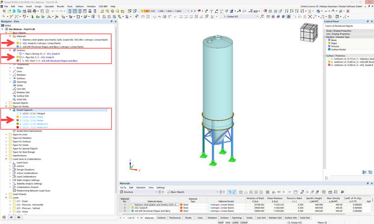
Here, an available RFEM 6 model (a
3D Steel Silo Structure
) is considered as the case study for the collapse simulation. In the current section, we need to define structural geometry, material properties, and boundary conditions (structural supports), which are shown in Image 1.
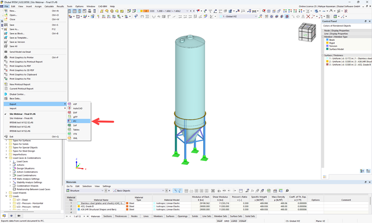
For the next stage, the IFC format needs to be exported from RFEM and imported to Blender (Image 2).
Step 2: BCB Blender Modeling
- Download and install Blender Software Version 3.5 and Blender Software Version 2.79 .
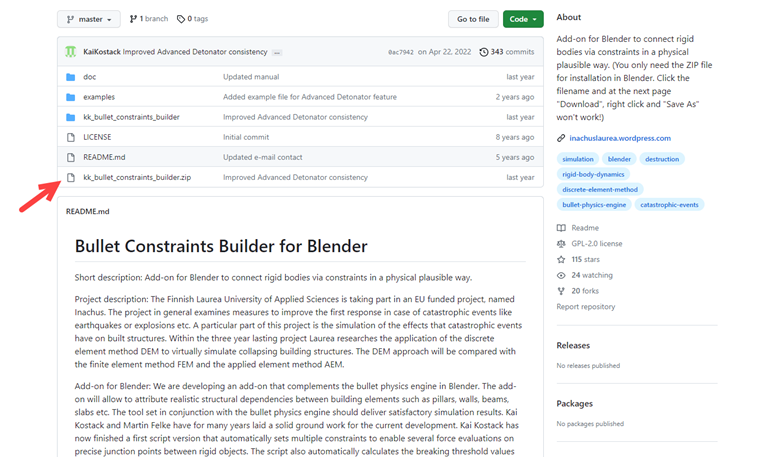
- Download and install Bullet Constraints Builder for Blender Version 2.79 (Image 3).
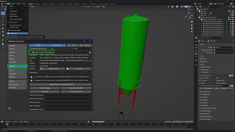
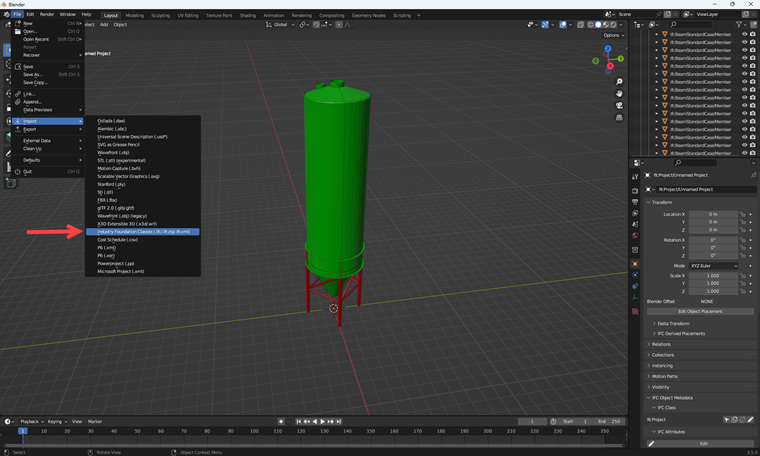
- Download and install the BlenderBIM Add-on to activate .IFC format import to Blender v. 3.5 (Image 3). The option to import IFC model format is available only after activating the BIM add-on in Blender's settings (Image 4).
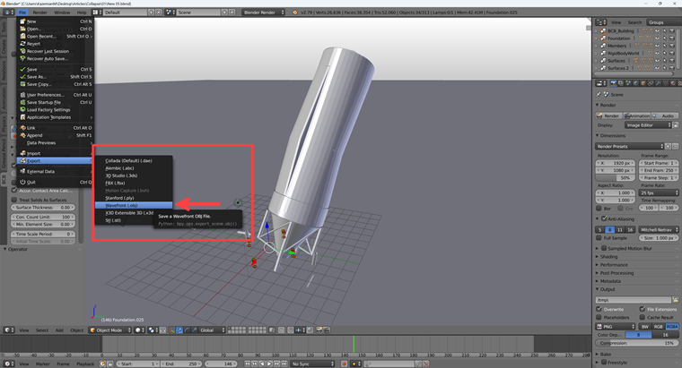
- Export the model as .OBJ format from Blender v. 3.5 and import to Blender v. 2.79 (Image 6).
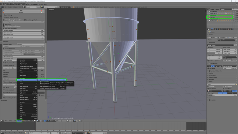
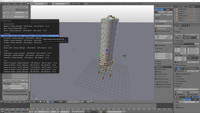
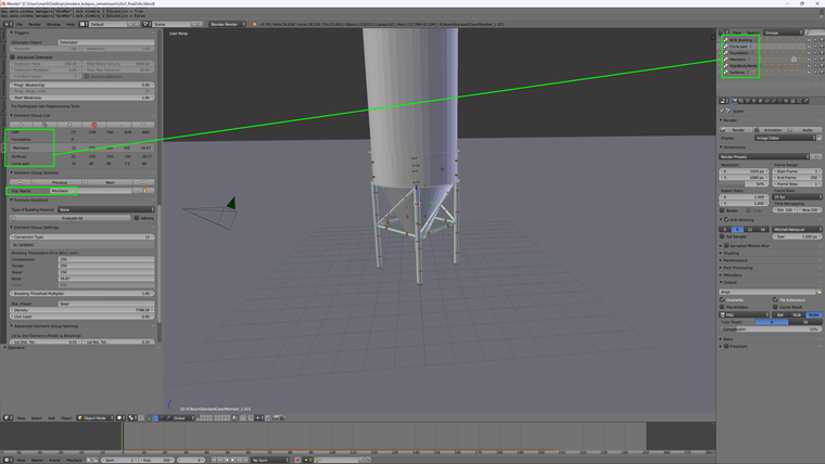
- Classification of the elements of models into "groups" and dividing them by type – beams, plates, foundations, and so on. For these groups, you can add properties in the table and element group list (Image 7). In order to set the parameters for individual groups, preset values for basic types of materials in the table can also be used, such as for reinforced concrete and steel structures (Image 8).
- To set up the groups, it is important that the groups in the table are named the same as the groups created in the Blender model (Image 9).
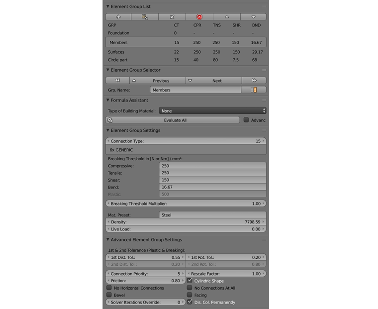
- Here is the information for beams set up in Image 10.
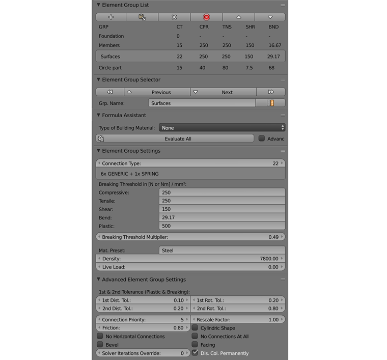
- The surface information is shown in Image 11.
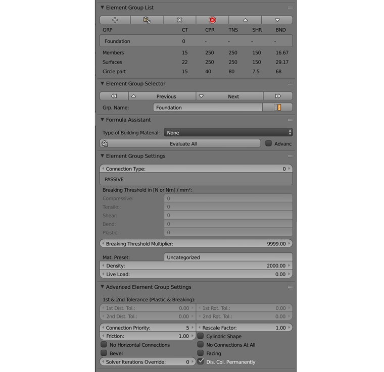
- The assumed boundary condition (support) and foundation information are shown in Image 12.
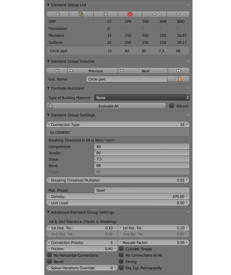
- Here, the information about the circular part is shown in Image 13.
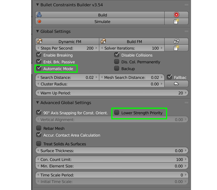
- Also, the general settings information is illustrated in Image 14.
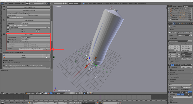
- Download Earthquake Time History Pattern and introduce to BCB Blender 2.79 as shown in Image 15.
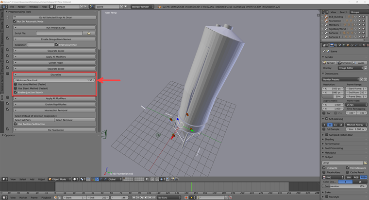
- The Minimum Size Limit value is defined as 1.50 in the discrete section (Image 16).
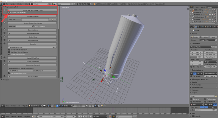
- To make sure that the Pre-processing Tools are included in the automatic mode, ensure that the box labeled "Run On Automatic Mode" in the header of the Pre-processing Tools is ticked. This will make the Pre-processing Tools part of the automatic mode (Image 17).
- It is recommended that you save the element configuration before moving on from this stage, as shown in Image 8. Every time the Blend file is opened, it will now be possible to reload the settings (Image 18).
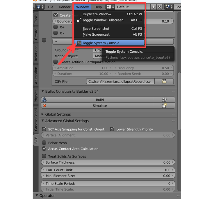
- The simulation's progress can be monitored via the system console window (Image 19), which should be kept open at all times. The system monitor can also be used to gather helpful data while troubleshooting, and then Press the "A" key on your keyboard to pick the complete model.
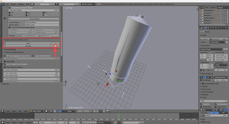
- After that, you need to press Build (Image 20), which will automatically run the Pre-processing tools before running the simulation.
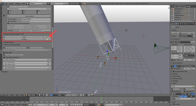
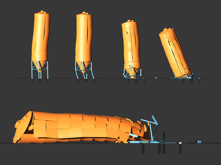
- And finally, the collapsed model is shown in Image 21. For the final render, you can use the latest version of Blender again. Below this article, you will find a demonstration of both our final file with the collapse in Blender 2.79 and the file with the settings for the final animation rendering in Blender 3.5.
Conclusion
In the current knowledge base article, we have described the goal of using the RFEM 6 and Blender with the Bullet Constraints Builder add-on to obtain a graphical representation of the collapse of a model based on real data of physical properties. RFEM 6 serves as the source of geometry and data for the simulation. This is another example of why it is important to maintain our programs as BIM Open, in order to achieve collaboration across software domains.