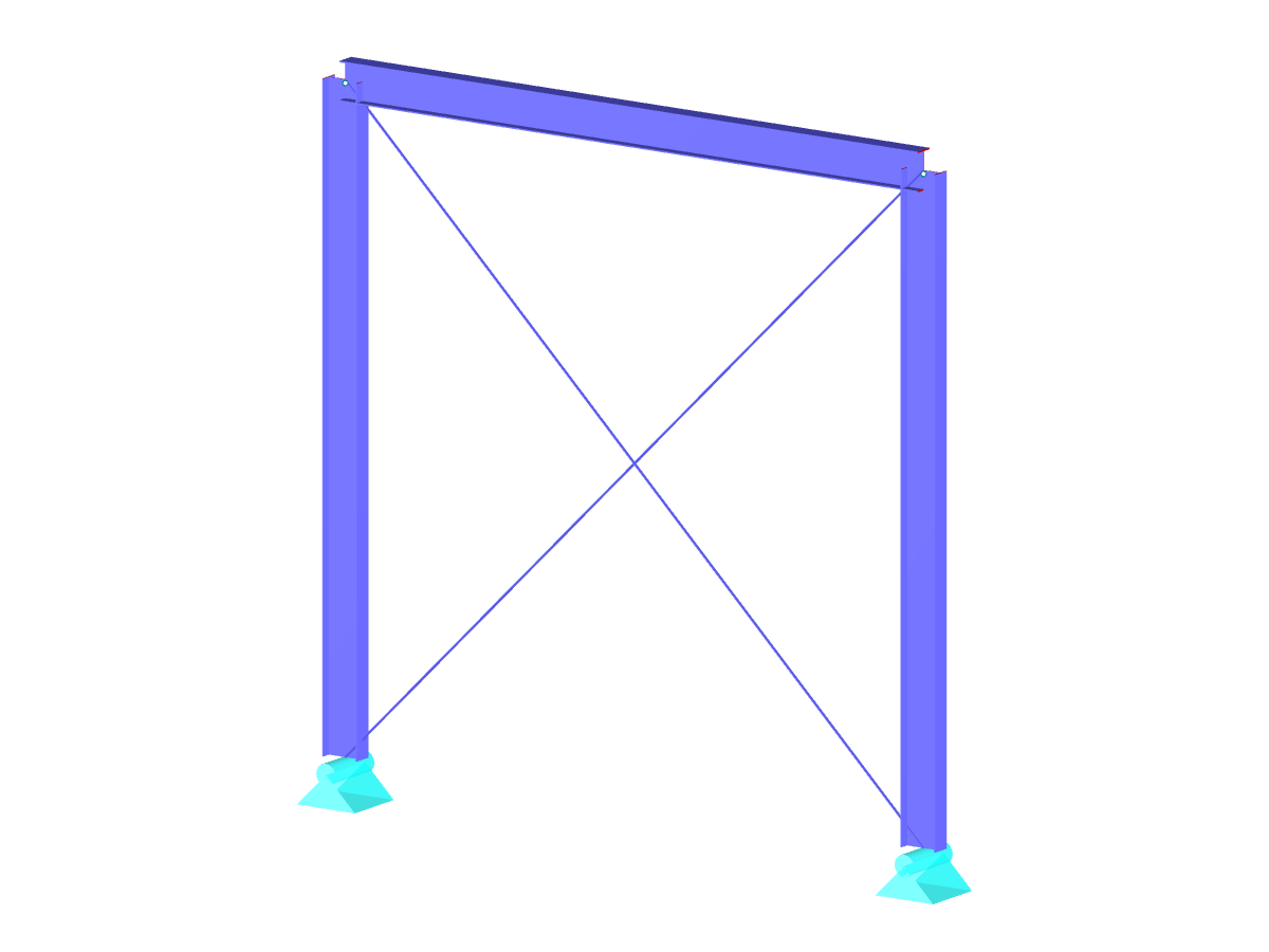
Symmetrical Two-Hinged Frame
Model to Download
Description
This model was used to demonstrate how to generate fewer load combinations by examining the results of all involved load cases.
Model Used in
Keywords
Combinatorics Reduction method Load combination Load case Number
Links
- Automatic Generation of Load Combinations in RFEM
- Automatic Generation of Load Combinations in RSTAB
Write Comment...
Write Comment...
- Views 107x
- Downloads 14x
- Updated 29 March 2021
Disclaimer

New
Less generated load combinations by reducing the load cases
To carry out a structural analysis for a structural system according to the current standards, it is necessary not only to deal with actions and resistances of structural components but also with the combinations of the actions. The most well -known actions in structural analysis are, for example, the permanently acting load case self -weight, the suddenly acting load cases wind and snow.

New
Depending on stiffness, mass, and damping, structures react differently to wind action.
- How do I apply prestress to tension members?
- Does the load generation also work for curved members?
- I would like to calculate and design "temporary structures." What do I need for this?
- I design timber components. The deformations of load combinations deviate from the manual calculation exactly by the factor of the material partial safety factor. Why?
- I often edit the reinforcement provided by the program. Adjusting the reinforcement by using coordinates takes much effort and time if having several beams in the model. Is there any way to speed up the reinforcement editing?
- Which programs can I use to calculate and design power plants?
- Which filter settings should be selected in the material library for concrete in order to perform design in RF‑CONCRETE according to the Swedish National Annex? In RFEM, there is no Swedish standard group available for the selection.
- I have analyzed two models of an inclined bored pile as a support with defined spring stiffness. A surface that can be moved horizontally (globally) is used for the force transmission. The bored pile in Model A is a support inclined by 15° with a spring stiffness of 2,000 kN/m in the axial direction. The bored pile of Model B is a support with the defined spring stiffnesses, divided into the respective horizontal and vertical components. The value of the spring stiffness is always the same (2,000 kN/m). In my opinion, both models are equivalent. Why are there different results in the deformation anyway?
- What is the best way to consider steel fiber reinforced concrete with the structural analysis program RFEM?
- I design a cross-section created in the SHAPE‑THIN program by using the RF‑STEEL EC3 add-on module, but the program shows the error message "ER006 Invalid type of c/t-part for cross-section of type General." What can I do?